Juniper jn0-664 practice test
Service Provider Routing and Switching, Professional (JNCIP-SP)
Question 1
Exhibit.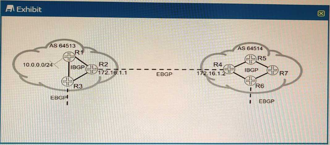
Referring to the exhibit; the 10.0.0.0/24 EBGP route is received on R5; however, the route is being
hidden.
What are two solutions that will solve this problem? (Choose two.)
- A. On R4, create a policy to change the BGP next hop to 172.16.1.1 and apply it to IBGP as an export policy.
- B. On R4, create a policy to change the BGP next hop to itself and apply it to IBGP as an export policy.
- C. On R4, add the internal IBGP interface prefixes to the BGP routing tables.
- D. On R4, add the external EBGP interface's prefix to the IGP routing tables.
Answer:
BD
Question 2
You are responding to an RFP for a new MPLS VPN implementation. The solution must use LDP for
signaling and support Layer 2 connectivity without using BGP The solution must be scalable and
support multiple VPN connections over a single MPLS LSP The customer wants to maintain all routing
for their Private network
In this scenario, which solution do you propose?
- A. circuit cross-connect
- B. BGP Layer 2 VPN
- C. LDP Layer 2 circuit
- D. translational cross-connect
Answer:
C
Explanation:
AToM (Any Transport over MPLS) is a framework that supports various Layer 2 transport types over
an MPLS network core. One of the transport types supported by AToM is LDP Layer 2 circuit, which is
a point-to-point Layer 2 connection that uses LDP for signaling and MPLS for forwarding. LDP Layer 2
circuit can support Layer 2 connectivity without using BGP and can be scalable and efficient by using
a single MPLS LSP for multiple VPN connections. The customer can maintain all routing for their
private network by using their own CE switches.
Question 3
Exhibit.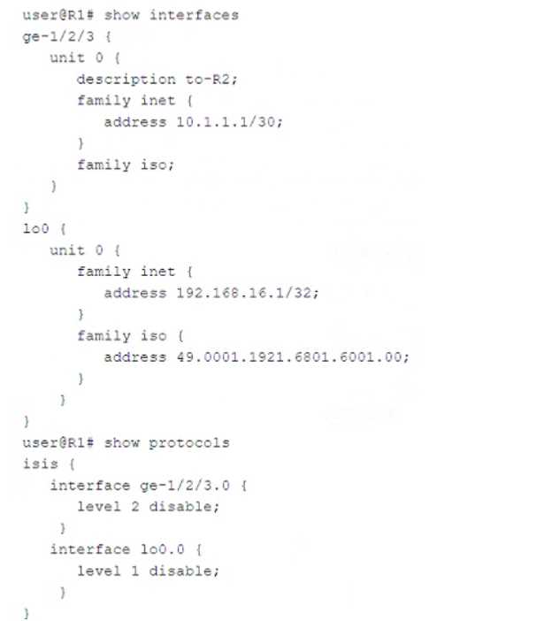
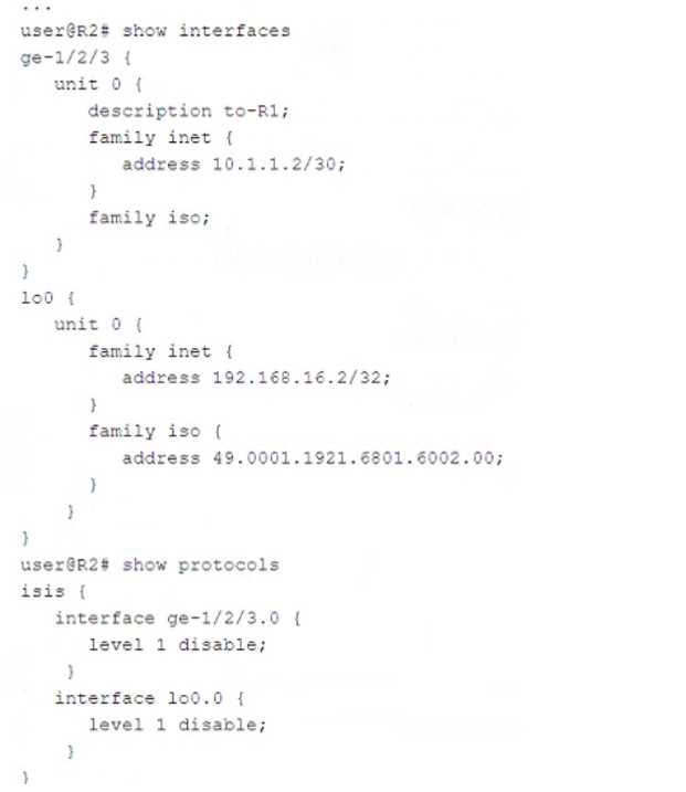
Referring to the exhibit, what must be changed to establish a Level 1 adjacency between routers R1
and R2?
- A. Change the level l disable parameter under the R1 protocols isis interface lo0.0 hierarchy to the level 2 disable parameter.
- B. Add IP addresses to the interface ge-1/2/3 unit 0 family iso hierarchy on both R1 and R2.
- C. Remove the level 1 disable parameter under the R2 protocols isis interface lo0.0 configuration hierarchy.
- D. Change the level 1 disable parameter under the R2 protocols isis interface ge-l/2/3.0 hierarchy to the level 2 disable parameter.
Answer:
D
Question 4
You are asked to protect your company's customers from amplification attacks. In this scenario, what
is Juniper's recommended protection method?
- A. ASN prepending
- B. BGP FlowSpec
- C. destination-based Remote Triggered Black Hole
- D. unicast Reverse Path Forwarding
Answer:
B
Question 5
Exhibit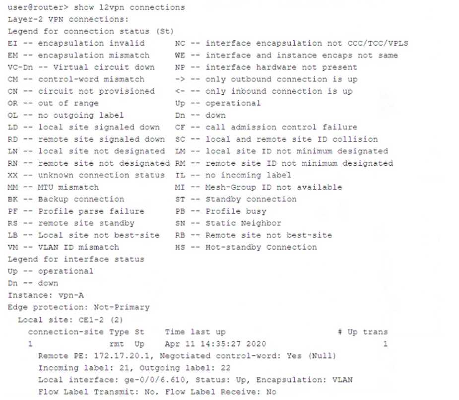
Which two statements about the output shown in the exhibit are correct? (Choose two.)
- A. The PE is attached to a single local site.
- B. The connection has not flapped since it was initiated.
- C. There has been a VLAN ID mismatch.
- D. The PE router has the capability to pop flow labels
Answer:
AB
Explanation:
The output is from the show l2vpn connections command on a Juniper router. This command is used
to verify the status of Layer 2 VPN (L2VPN) pseudowires between Provider Edge (PE) routers.
Breakdown of Key Information:
Instance: vpn-A
This is the L2VPN instance being monitored.
Connection Status (St)
The connection status is "Up", meaning the pseudowire is operational.
Local Site: CE1-2 (2)
The PE router is attached to a single local site (CE1-2).
Uptime & Connection Flaps
The output shows the last time the connection was up:
Time last up: Apr 11 14:35:27 2020
The "# Up trans" value is 1, meaning this connection has been established once and has not flapped
since it was initiated.
VLAN ID Mismatch Check
The legend includes "VM – VLAN ID mismatch", but this status is not present in the connection
output.
This means there is NO VLAN ID mismatch.
Flow Labels
The Flow Label Transmit is No, and the Flow Label Receive is No.
This means the PE router does NOT have the capability to pop flow labels.
Question 6
Exhibit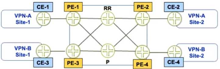
Referring to the exhibit, PE-1 and PE-2 are getting route updates for VPN-B when neither of them
service that VPN
Which two actions would optimize this process? (Choose two.)
- A. Configure the resolution rib bgp.l3vpn.0 resolution-ribs inet.0 statement on the PEs.
- B. Configure the family route-target statement on the RR.
- C. Configure the resolution rib bgp.l3vpn.0 resolution-ribs inet.0 statement on the RR.
- D. Configure the family route-target statement on the PEs.
Answer:
BC
Explanation:
BGP route target filtering can be configured on PE devices or on route reflectors (RRs). Configuring
BGP route target filtering on RRs is more efficient and scalable, as it reduces the number of BGP
sessions and updates between PE devices. To configure BGP route target filtering on RRs, the
following steps are required:
Configure the family route-target statement under the BGP group or neighbor configuration on the
RRs. This enables the exchange of the route-target address family between the RRs and their clients
(PE devices). Configure the resolution rib bgp.l3vpn.0 resolution-ribs inet.0 statement under the
routing-options configuration on the RRs. This enables the RRs to resolve next hops for VPN routes
using the inet.0 routing table.
Question 7
Which two EVPN route types are used to advertise a multihomed Ethernet segment? (Choose two )
- A. Type 1
- B. Type 3
- C. Type 4
- D. Type 2
Answer:
AC
Explanation:
EVPN is a solution that provides Ethernet multipoint services over MPLS networks. EVPN uses BGP to
distribute endpoint provisioning information and set up pseudowires between PE devices. EVPN uses
different route types to convey different information in the control plane. The following are the main
EVPN route types:
Type 1 - Ethernet Auto-Discovery Route: This route type is used for network-wide messaging and
discovery of other PE devices that are part of the same EVPN instance. It also carries information
about the redundancy mode and load balancing algorithm of the PE devices.
Type 2 - MAC/IP Advertisement Route: This route type is used for MAC and IP address learning and
advertisement between PE devices. It also carries information about the Ethernet segment identifier
(ESI) and the label for forwarding traffic to the MAC or IP address.
Type 3 - Inclusive Multicast Ethernet Tag Route: This route type is used for broadcast, unknown
unicast, and multicast (BUM) traffic forwarding. It also carries information about the multicast group
and the label for forwarding BUM traffic.
Type 4 - Ethernet Segment Route: This route type is used for multihoming scenarios, where a CE
device is connected to more than one PE device. It also carries information about the ESI and the
designated forwarder (DF) election process.
Question 8
Which statement is correct about IS-IS when it performs the Dijkstra algorithm?
- A. The local router moves its own local tuples into the candidate database
- B. When a new neighbor ID in the tree database matches a router ID in the LSDB, the neighbor ID is moved to the candidate database
- C. Tuples with the lowest cost are moved from the tree database to the LSDB.
- D. The algorithm will stop processing once the tree database is empty.
Answer:
B
Explanation:
The Dijkstra algorithm in IS-IS operates as follows:
Tree Database Initialization: The local router (root) is added to the tree database with a cost of 0.
Candidate Database Population: Neighbors of the root (from the LSDB) are placed into the candidate
database with their associated costs.
Processing Nodes: The node with the lowest cost in the candidate database is moved to the tree
database.
Neighbor Evaluation: For each neighbor of the newly added node (from the LSDB), if the neighbor is
not already in the tree or candidate database, it is added to the candidate database. If it exists in the
candidate with a higher cost, it is updated with the lower cost.
Termination: The algorithm stops when the candidate database is empty, ensuring all shortest paths
are computed.
Analysis of Options:
A . Incorrect. The local router is placed directly into the tree database, not the candidate database.
B . Correct (with context). When a node is added to the tree database, its neighbors (existing in the
LSDB) are evaluated. If these neighbors are not already in the tree or candidate database, they
are added (not "moved") to the candidate database. The wording "moved" is technically inaccurate,
but this option aligns closest with the process of populating the candidate database using LSDB
entries during tree database processing.
C . Incorrect. Tuples (nodes) with the lowest cost are moved from the candidate database to
the tree database, not from the tree to the LSDB. The LSDB remains static during SPF computation.
D . Incorrect. The algorithm stops when the candidate database is empty, not the tree database. The
tree database grows as nodes are processed.
Question 9
Exhibit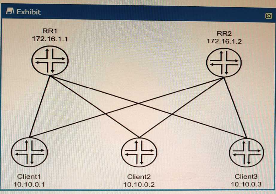
The environment is using BGP All devices are in the same AS with reachability redundancy Referring
to the exhibit, which statement is correct?
- A. RR1 is peered to Client2 and RR2
- B. RR2 is in an OpenConfirm State until RR1 becomes unreachable.
- C. Client1 is peered to Client2 and Client3.
- D. Peering is dynamically discovered between all devices.
Answer:
A
Explanation:
BGP route reflectors are BGP routers that are allowed to ignore the IBGP loop avoidance rule and
advertise IBGP learned routes to other IBGP peers under specific conditions. BGP route reflectors can
reduce the number of IBGP sessions and updates in a network by eliminating the need for a full
mesh of IBGP peers. BGP route reflectors can have three types of peerings:
EBGP neighbor: A BGP router that belongs to a different autonomous system (AS) than the route
reflector.
IBGP client neighbor: An IBGP router that receives reflected routes from the route reflector. A client
does not need to peer with other clients or non-clients.
IBGP non-client neighbor: An IBGP router that does not receive reflected routes from the route
reflector. A non-client needs to peer with other non-clients and the route reflector.
In the exhibit, we can see that RR1 and RR2 are route reflectors in the same AS with reachability
redundancy. They have two types of peerings: EBGP neighbors (R1 and R4) and IBGP client neighbors
(Client1, Client2, and Client3). RR1 and RR2 are also peered with each other as IBGP non-client
neighbors.
Question 10
You are configuring a BGP signaled Layer 2 VPN across your MPLS enabled core network. Your PE-2
device connects to two sites within the s VPN
In this scenario, which statement is correct?
- A. By default on PE-2, the site's local ID is automatically assigned a value of 0 and must be configured to match the total number of attached sites.
- B. You must create a unique Layer 2 VPN routing instance for each site on the PE-2 device.
- C. You must use separate physical interfaces to connect PE-2 to each site.
- D. By default on PE-2, the remote site IDs are automatically assigned based on the order that you add the interfaces to the site configuration.
Answer:
D
Explanation:
BGP Layer 2 VPNs use BGP to distribute endpoint provisioning information and set up pseudowires
between PE devices. BGP uses the Layer 2 VPN (L2VPN) Routing Information Base (RIB) to store
endpoint provisioning information, which is updated each time any Layer 2 virtual forwarding
instance (VFI) is configured. The prefix and path information is stored in the L2VPN database, which
allows BGP to make decisions about the best path.
In BGP Layer 2 VPNs, each site has a unique site ID that identifies it within a VFI. The site ID can be
manually configured or automatically assigned by the PE device. By default, the site ID is
automatically assigned based on the order that you add the interfaces to the site configuration. The
first interface added to a site configuration has a site ID of 1, the second interface added has a site ID
of 2, and so on.
Option D is correct because by default on PE-2, the remote site IDs are automatically assigned based
on the order that you add the interfaces to the site configuration. Option A is not correct because by
default on PE-2, the site’s local ID is automatically assigned a value of 0 and does not need to be
configured to match the total number of attached sites. Option B is not correct because you do not
need to create a unique Layer 2 VPN routing instance for each site on the PE-2 device. You can create
one routing instance for all sites within a VFI. Option C is not correct because you do not need to use
separate physical interfaces to connect PE-2 to each site. You can use subinterfaces or service
instances on a single physical interface.
Question 11
Exhibit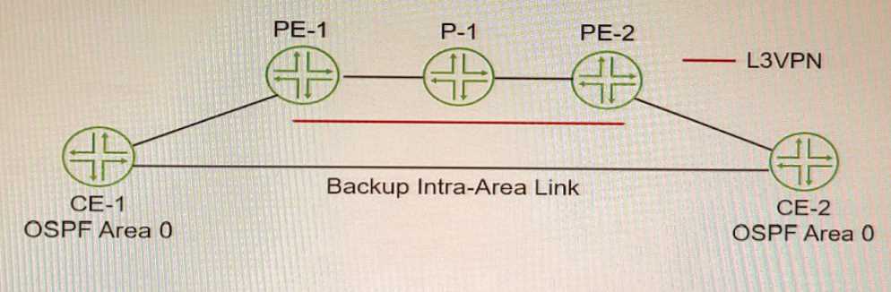
You must ensure that the VPN backbone is preferred over the back door intra-area link as long as the
VPN is available. Referring to the exhibit, which action will accomplish this task?
- A. Configure an import routing policy on the CE routers that rejects OSPF routes learned on the backup intra-area link.
- B. Enable OSPF traffic-engineering.
- C. Configure the OSPF metric on the backup intra-area link that is higher than the L3VPN link.
- D. Create an OSPF sham link between the PE routers.
Answer:
D
Explanation:
A sham link is a logical link between two PE routers that belong to the same OSPF area but are
connected through an L3VPN. A sham link makes the PE routers appear as if they are directly
connected, and prevents OSPF from preferring an intra-area back door link over the VPN
backbone.
To create a sham link, you need to configure the local and remote addresses of the PE
routers under the [edit protocols ospf area area-id] hierarchy level1
.
https://www.juniper.net/documentation/us/en/software/junos/ospf/topics/topic-map/configuring-ospfv2-sham-links.html
Question 12
Exhibit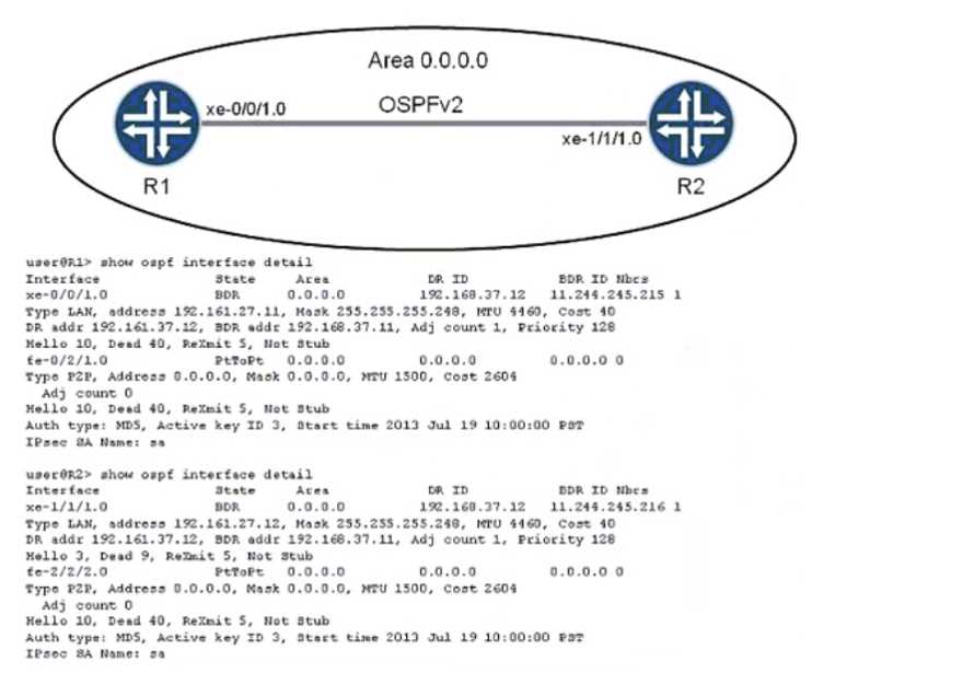
Which two statements are true about the OSPF adjacency displayed in the exhibit? (Choose two.)
- A. There is a mismatch in the hello interval parameter between routers R1 and R2
- B. There is a mismatch in the dead interval parameter between routers R1 and R2.
- C. There is a mismatch in the OSPF hold timer parameter between routers R1 and R2.
- D. There is a mismatch in the poll interval parameter between routers R1 and R2.
Answer:
AB
Explanation:
The hello interval is the time interval between two consecutive hello packets sent by an OSPF router
on an interface. The dead interval is the time interval after which a neighbor is declared down if no
hello packets are received from it. These parameters must match between two OSPF routers for
them to form an adjacency. In the exhibit, router R1 has a hello interval of 10 seconds and a dead
interval of 40 seconds, while router R2 has a hello interval of 30 seconds and a dead interval of 120
seconds. This causes a mismatch and prevents them from becoming neighbors
.
Question 13
Exhibit
user@Rl show configuration interpolated-profile { interpolate {
fill-level [ 50 75 drop—probability [ > }
class-of-service drop-profiles
];
20 60 ];
Which two statements are correct about the class-of-service configuration shown in the exhibit?
(Choose two.)
- A. The drop probability jumps immediately from 20% to 60% when the queue level reaches 75% full.
- B. The drop probability gradually increases from 20% to 60% as the queue level increases from 50% full to 75% full
- C. To use this drop profile, you reference it in a scheduler.
- D. To use this drop profile, you apply it directly to an interface.
Answer:
BC
Explanation:
class-of-service (CoS) is a feature that allows you to prioritize and manage network traffic based on
various criteria, such as application type, user group, or packet loss priority. CoS uses different
components to classify, mark, queue, schedule, shape, and drop traffic according to the configured
policies.
One of the components of CoS is drop profiles, which define how packets are dropped when a queue
is congested. Drop profiles use random early detection (RED) algorithm to drop packets randomly
before the queue is full, which helps to avoid global synchronization and improve network
performance. Drop profiles can be discrete or interpolated. A discrete drop profile maps a specific fill
level of a queue to a specific drop probability. An interpolated drop profile maps a range of fill levels
of a queue to a range of drop probabilities and interpolates the values in between.
In the exhibit, we can see that the class-of-service configuration shows an interpolated drop profile
with two fill levels (50 and 75) and two drop probabilities (20 and 60). Based on this configuration,
we can infer the following statements:
The drop probability jumps immediately from 20% to 60% when the queue level reaches 75% full.
This is not correct because the drop profile is interpolated, not discrete. This means that the drop
probability gradually increases from 20% to 60% as the queue level increases from 50% full to 75%
full. The drop probability for any fill level between 50% and 75% can be calculated by using linear
interpolation formula.
The drop probability gradually increases from 20% to 60% as the queue level increases from 50% full
to 75% full. This is correct because the drop profile is interpolated and uses linear interpolation
formula to calculate the drop probability for any fill level between 50% and 75%. For example, if the
fill level is 60%, the drop probability is 28%, which is calculated by using the formula: (60 - 50) / (75 -
50) * (60 - 20) + 20 = 28.
To use this drop profile, you reference it in a scheduler. This is correct because a scheduler is a
component of CoS that determines how packets are dequeued from different queues and
transmitted on an interface. A scheduler can reference a drop profile by using the random-detect
statement under the [edit class-of-service schedulers] hierarchy level. For example: scheduler test {
transmit-rate percent 10; buffer-size percent 10; random-detect test-profile; }
To use this drop profile, you apply it directly to an interface. This is not correct because a drop profile
cannot be applied directly to an interface. A drop profile can only be referenced by a scheduler,
which can be applied to an interface by using the scheduler-map statement under the [edit class-of-
service interfaces] hierarchy level. For example: interfaces ge-0/0/0 { unit 0 { scheduler-map test-
map; } }
Question 14
Which two statements are correct about IS-IS interfaces? (Choose two.)
- A. If a point-to-point interface is in both L1 and L2, separate hello messages are sent for each level.
- B. If a point-to-point interface is in both 11 and L2, one combined hello message is sent for both levels.
- C. If a broadcast interface is in both L1 and L2, separate hello messages are sent for each level.
- D. If a broadcast interface is in both L1 and L2, one combined hello message is sent for both levels.
Answer:
BC
Explanation:
Intermediate System to Intermediate System (IS-IS) is a link-state routing protocol that supports
Level 1 (L1), Level 2 (L2), or both (L1/L2) operations. The way IS-IS sends Hello (IIH) packets depends
on whether the interface is point-to-point (P2P) or broadcast (LAN).
Evaluating the Answer Choices
✅
Option A: "If a point-to-point interface is in both L1 and L2, separate hello messages are sent for
each level."
Incorrect!
On point-to-point (P2P) interfaces, only one combined Hello message is sent for both L1 and L2.
IS-IS P2P Hellos include both Level 1 and Level 2 TLVs in the same message.
Reference: Juniper IS-IS documentation confirms that P2P links use a single Hello message with both
levels included.
❌
This statement is incorrect.
✅
Option B: "If a point-to-point interface is in both L1 and L2, one combined hello message is sent
for both levels."
Correct!
On point-to-point (P2P) links, IS-IS sends a single Hello message that includes TLVs for both L1 and L2.
This reduces overhead and simplifies adjacency formation.
✅
This statement is correct.
✅
Option C: "If a broadcast interface is in both L1 and L2, separate hello messages are sent for each
level."
Correct!
On broadcast (LAN) interfaces, IS-IS sends separate Hello messages for L1 and L2.
This is because L1 and L2 use separate Designated IS (DIS) elections and different multicast
addresses:
L1 Hellos: Sent to AllL1IS (01:80:C2:00:00:14)
L2 Hellos: Sent to AllL2IS (01:80:C2:00:00:15)
Reference: Juniper IS-IS Configuration Guide confirms that broadcast interfaces send separate L1 and
L2 Hello messages.
✅
This statement is correct.
✅
Option D: "If a broadcast interface is in both L1 and L2, one combined hello message is sent for
both levels."
Incorrect!
As stated above, IS-IS sends separate Hello messages for L1 and L2 on broadcast interfaces because
they have independent DIS elections.
❌
This statement is incorrect.
Final Answer:
✅
B. If a point-to-point interface is in both L1 and L2, one combined hello message is sent for both
levels.
✅
C. If a broadcast interface is in both L1 and L2, separate hello messages are sent for each level.
Verification from Juniper Documentation
Juniper IS-IS Configuration Guide confirms:
Point-to-Point (P2P) interfaces send one combined Hello for both levels.
Broadcast interfaces send separate L1 and L2 Hellos due to separate DIS elections.
RFC 1195 (IS-IS Extensions for IPv4) specifies that broadcast networks require distinct Hellos per
level.
Question 15
Exhibit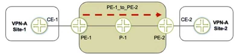
Referring to the exhibit, a working L3VPN exists that connects VPN-A sites CoS is configured correctly
to match on the MPLS EXP bits of the LSP, but when traffic is sent from Site-1 to Site-2, PE-2 is not
classifying the traffic correctly
What should you do to solve the problem?
- A. Configure the explicit-null statement on PE-1.
- B. Configure the explicit-null statement on PE-2
- C. Configure VPN prefix mapping for the PE-1_to_PE-2 LSP
- D. Set a static CoS value for the PE-1_to_PE-2 LSP
Answer:
B
Explanation:
Understanding the Problem in MPLS CoS Classification
How EXP Bits Are Used for CoS in MPLS
Traffic is sent from VPN-A Site-1 → CE-1 → PE-1 → P-1 → PE-2 → CE-2.
The MPLS LSP (Label Switched Path) from PE-1 to PE-2 is expected to carry MPLS EXP bits, which are
used for Class of Service (CoS) classification.
PE-2 should classify traffic based on EXP bits received in the MPLS label.
What Happens with PHP (Penultimate Hop Popping)?
By default, the penultimate router (P-1) pops the top MPLS label before sending the packet to PE-2.
Since the EXP bits are in the top MPLS label, they get removed along with the label.
This means that PE-2 no longer sees the correct EXP bits, leading to incorrect traffic classification.
Solution: Configure Explicit-Null on PE-2
Explicit Null (explicit-null) must be configured on PE-2 to ensure that P-1 does NOT remove the MPLS
label.
Instead of removing the label, P-1 will send a label of 0 (for IPv4) or 2 (for IPv6) to PE-2.
This preserves the MPLS EXP bits, allowing PE-2 to classify the traffic correctly.
Evaluating the Answer Choices Again
✅
B. Configure the explicit-null statement on PE-2.
Correct, because:
PE-2 is the egress LSR, where Ultimate Hop Popping (UHP) must be enabled.
Configuring explicit-null ensures that P-1 does not remove the label, preserving the EXP bits for CoS
classification at PE-2.
Configuration on PE-2:
set protocols mpls explicit-null
Juniper Documentation Reference:
"Explicit-null must be configured on the egress LSR to prevent PHP from removing the top MPLS
label, thereby preserving the EXP bits."
❌
A. Configure the explicit-null statement on PE-1.
Incorrect, because:
Explicit-null must be configured on the egress LSR (PE-2), not the ingress LSR (PE-1).
PE-1 only labels the traffic but does not control PHP behavior on P-1.
❌
C. Configure VPN prefix mapping for the PE-1_to_PE-2 LSP.
Incorrect, because:
VPN prefix mapping is used for mapping VPN routes to LSPs but does not solve the EXP bit issue.
The problem here is label removal (PHP), not route mapping.
❌
D. Set a static CoS value for the PE-1_to-PE-2 LSP.
Incorrect, because:
This does not preserve the original EXP bits, it only applies a static CoS value.
It’s a workaround, not a fix.
✅
Final Answer:
B. Configure the explicit-null statement on PE-2.
Explanation:
Key Takeaways
Penultimate Hop Popping (PHP) removes the outer MPLS label at P-1, which also removes the EXP
bits used for CoS classification.
To keep EXP bits intact, configure explicit-null on the egress PE (PE-2).
This forces P-1 to send a label (0 for IPv4, 2 for IPv6) to PE-2, preserving the EXP bits for CoS
classification.
Official Juniper Documentation Reference
Juniper MPLS CoS and PHP Behavior Guide
"To retain CoS EXP bits at the egress LSR, configure explicit-null on the egress PE. This prevents PHP
from stripping the MPLS label before reaching the final PE router."