Juniper jn0-637 practice test
Security, Professional (JNCIP-SEC)
Question 1
You are enabling advanced policy-based routing. You have configured a static route that has a next
hop from the inet.0 routing table. Unfortunately, this static route is not active in your routing
instance.
In this scenario, which solution is needed to use this next hop?
- A. Use RIB groups.
- B. Use filter-based forwarding.
- C. Use transparent mode.
- D. Use policies.
Answer:
A
Explanation:
To enable advanced policy-based routing in Junos OS and activate a static route with a next-hop
address in the inet.0 table within your routing instance, you should utilize RIB groups. RIB groups
allow you to import routes from one routing table to another. In this scenario, the static route within
the routing instance needs access to the inet.0 routes, which is facilitated by configuring a RIB group.
Juniper’s documentation outlines RIB groups as a necessary component for handling instances where
routes need to be shared across routing tables, thereby ensuring seamless traffic flow through
specified routes. For more details, refer to the Juniper Networks Documentation on RIB Groups.
In Junos OS for SRX Series devices, when enabling advanced policy-based routing and configuring a
static route with a next-hop from the inet.0 routing table, the issue arises because the static route is
not being used in the routing instance. This is a common scenario when the next-hop belongs to a
different routing table or instance, and the routing instance is not aware of that next-hop.
To resolve this, RIB (Routing Information Base) groups are used. RIB groups allow routes from one
routing table (RIB) to be shared or imported into another routing table. This means that the routing
instance can import the necessary routes from inet.0 and make them available for the routing
instance where the policy-based routing is applied.
Detailed Steps:
Configure the Static Route: First, configure the static route pointing to the next-hop in inet.0. Here’s
an example:
bash
set routing-options static route 10.1.1.0/24 next-hop 192.168.1.1
This static route will be placed in the inet.0 routing table by default.
Create and Apply a RIB Group: To import routes from inet.0 into the routing instance, create a RIB
group configuration. This will allow the static route from inet.0 to be visible within the routing
instance.
Example configuration for the RIB group:
bash
set routing-options rib-groups RIB-GROUP import-rib inet.0
set routing-options rib-groups RIB-GROUP import-rib <routing-instance-name>.inet.0
This configuration ensures that routes from inet.0 are imported into the specified routing instance.
Apply the RIB Group to the Routing Instance: Once the RIB group is configured, apply it to the
appropriate routing instance:
bash
set routing-instances <routing-instance-name> routing-options rib-group RIB-GROUP
Verify Configuration: Use the following command to verify that the static route has been imported
into the routing instance:
bash
show route table <routing-instance-name>.inet.0
The output should now display the static route imported from inet.0.
Juniper Security Reference:
RIB Groups Overview: Juniper's documentation provides detailed information on how RIB groups
function and how to use them to share routes between different routing tables. This is essential for
scenarios involving policy-based routing where routes from one instance (like inet.0) need to be
available in another instance. Reference: Juniper Networks Documentation on RIB Groups.
By using RIB groups, you ensure that the static route from inet.0 is available in the appropriate
routing instance for policy-based routing to function correctly. This avoids the need for other
methods like filter-based forwarding or transparent mode, which do not address the specific issue of
static route visibility across routing instances.
Question 2
Exhibit: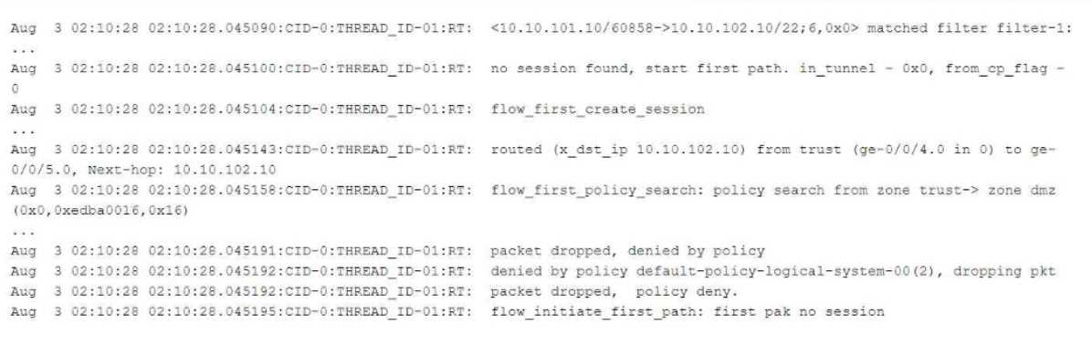
Referring to the flow logs exhibit, which two statements are correct? (Choose two.)
- A. The packet is dropped by the default security policy.
- B. The packet is dropped by a configured security policy.
- C. The data shown requires a traceoptions flag of host-traffic.
- D. The data shown requires a traceoptions flag of basic-datapath.
Answer:
AD
Explanation:
Understanding the Flow Log Output:
From the flow logs in the exhibit, we can observe the following key events:
The session creation was initiated (flow_first_create_session), but the policy search failed
(flow_first_policy_search), which implies that no matching policy was found between the zones
involved (zone trust-> zone dmz).
The packet was dropped with the reason "denied by policy." This shows that the packet was dropped
either due to no matching security policy or because the default policy denies the traffic (packet
dropped, denied by policy).
The line denied by policy default-policy-logical-system-00(2) indicates that the default security policy
is responsible for denying the traffic, confirming that no explicit security policy was configured to
allow this traffic.
Explanation of Answer A (Dropped by the default security policy):
The log message clearly states that the packet was dropped by the default security policy (default-
policy-logical-system-00). In Junos, when a session is attempted between two zones and no explicit
policy exists to allow the traffic, the default policy is to deny the traffic. This is a common behavior in
Junos OS when a security policy does not explicitly allow traffic between zones.
Explanation of Answer D (Requires traceoptions flag of basic-datapath):
The information displayed in the log involves session creation, flow policy search, and packet
dropping due to policy violations, which are all part of basic packet processing in the data path. This
type of information is logged when the traceoptions flag is set to basic-datapath. The basic-datapath
traceoption provides detailed information about the forwarding process, including policy lookups
and packet drops, which is precisely what we see in the exhibit.
The traceoptions flag host-traffic (Answer C) is incorrect because host-traffic is typically used for
traffic destined to or generated from the Junos device itself (e.g., SSH or SNMP traffic to the SRX
device), not for traffic passing through the device.
To capture flow processing details like those shown, you need the basic-datapath traceoptions flag,
which provides details about packet forwarding and policy evaluation.
Step-by-Step Configuration for Tracing (Basic-Datapath):
Enable flow traceoptions:
To capture detailed information about how traffic is being processed, including policy lookups and
flow session creation, enable traceoptions for the flow.
bash
set security flow traceoptions file flow-log
set security flow traceoptions flag basic-datapath
Apply the configuration and commit:
bash
commit
View the logs:
Once enabled, you can check the trace logs for packet flows, policy lookups, and session creation
details:
bash
show log flow-log
This log will contain information similar to the exhibit, including session creation attempts and
packet drops due to security policy.
Juniper Security Reference:
Default Security Policies: Juniper SRX devices have a default security policy to deny all traffic that is
not explicitly allowed by user-defined policies. This is essential for security best practices. Reference:
Juniper Networks Documentation on Security Policies.
Traceoptions for Debugging Flows: Using traceoptions is crucial for debugging and understanding
how traffic is handled by the SRX, particularly when issues arise from policy misconfigurations or
routing. Reference: Juniper Traceoptions.
By using the basic-datapath traceoptions, you can gain insights into how the device processes traffic,
including policy lookups, route lookups, and packet drops, as demonstrated in the exhibit.
Question 3
Exhibit: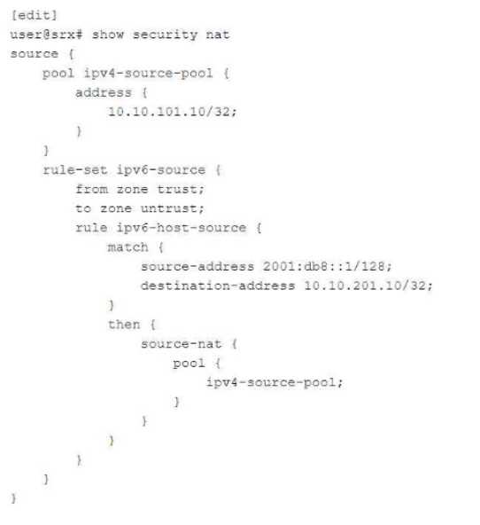
You are configuring NAT64 on your SRX Series device. You have committed the configuration shown
in the exhibit. Unfortunately, the communication with the 10.10.201.10 server is not working. You
have verified that the interfaces, security zones, and security policies are all correctly configured.
In this scenario, which action will solve this issue?
- A. Configure source NAT to translate return traffic from IPv4 address to the IPv6 address of your source device.
- B. Configure proxy-ARP on the external IPv4 interface for the 10.10.201.10/32 address.
- C. Configure proxy-NDP on the IPv6 interface for the 2001:db8::1/128 address.
- D. Configure destination NAT to translate return traffic from the IPv4 address to the IPv6 address of your source device.
Answer:
D
Question 4
What are three core components for enabling advanced policy-based routing? (Choose three.)
- A. Filter-based forwarding
- B. Routing options
- C. Routing instance
- D. APBR profile
- E. Policies
Answer:
ACD
Explanation:
To enable Advanced Policy-Based Routing (APBR) on SRX Series devices, three key components are
necessary: filter-based forwarding, routing instances, and APBR profiles. Filter-based forwarding is
utilized to direct specific traffic flows to a routing instance based on criteria set by a policy. Routing
instances allow the traffic to be managed independently of the main routing table, and APBR profiles
define how and when traffic should be forwarded. These elements ensure that APBR is flexible and
tailored to the network’s requirements. Refer to Juniper's APBR Documentation for more details.
Advanced policy-based routing (APBR) in Juniper's SRX devices allows the selection of different paths
for traffic based on policies, rather than relying purely on routing tables. To enable APBR, the
following core components are required:
Filter-based Forwarding (Answer A): Filter-based forwarding (FBF) is a technique used to forward
traffic based on policies rather than the default routing table. It is essential for enabling APBR, as it
helps match traffic based on filters and directs it to specific routes.
Configuration Example:
bash
set firewall family inet filter FBF match-term source-address 192.168.1.0/24
set firewall family inet filter FBF then routing-instance custom-routing-instance
Routing Instance (Answer C): A routing instance is required to define the separate routing table used
by APBR. You can create multiple routing instances and assign traffic to these instances based on
policies. The traffic will then use the routes defined within the specific routing instance.
Configuration Example:
bash
set routing-instances custom-routing-instance instance-type forwarding
set routing-instances custom-routing-instance routing-options static route 0.0.0.0/0 next-hop
10.10.10.1
APBR Profile (Answer D): The APBR profile defines the rules and policies for advanced policy-based
routing. It allows you to set up conditions such as traffic type, source/destination address, and port,
and then assign actions such as redirecting traffic to specific routing instances.
Configuration Example:
bash
set security forwarding-options advanced-policy-based-routing profile apbr-profile match application
http
set security forwarding-options advanced-policy-based-routing profile apbr-profile then routing-
instance custom-routing-instance
Other Components:
Routing Options (Answer B) are not a core component of APBR, as routing options define the general
behavior of the routing table and protocols. However, APBR works by overriding these default
routing behaviors using policies.
Policies (Answer E) are crucial in many network configurations but are not a core component of
enabling APBR. APBR specifically relies on profiles rather than standard security policies.
Juniper Security Reference:
Advanced Policy-Based Routing (APBR): Juniper’s APBR is a powerful tool that allows routing based
on specific traffic characteristics rather than relying on static routing tables. APBR ensures that
specific types of traffic can take alternate paths based on business or network needs. Reference:
Juniper Networks APBR Documentation.
Question 5
You want to bypass IDP for traffic destined to social media sites using APBR, but it is not working and
IDP is dropping the session.
What are two reasons for this problem? (Choose two.)
- A. The session did not properly reclassify midstream to the correct APBR rule.
- B. IDP disable is not configured on the APBR rule.
- C. The application services bypass is not configured on the APBR rule.
- D. The APBR rule does a match on the first packet.
Answer:
AC
Explanation:
Explanation of Answer A (Session Reclassification):
APBR (Advanced Policy-Based Routing) requires the session to be classified based on the specified
rule, which can change midstream as additional packets are processed. If the session was already
established before the APBR rule took effect, the traffic may not be correctly reclassified to match the
new APBR rule, leading to IDP (Intrusion Detection and Prevention) processing instead of being
bypassed. This can occur especially when the session was already established before the rule change.
Explanation of Answer C (Application Services Bypass):
For APBR to work and bypass the IDP service, the application services bypass must be explicitly
configured. Without this configuration, the APBR rule may redirect the traffic, but the IDP service will
still inspect and potentially drop the traffic. This is especially important for traffic destined for specific
sites like social media platforms where bypassing IDP is desired.
Example configuration for bypassing IDP services:
bash
set security forwarding-options advanced-policy-based-routing profile <profile-name> application-
services-bypass
Step-by-Step Resolution:
Reclassify the Session Midstream:
If the traffic was already being processed before the APBR rule was applied, ensure that the session is
reclassified by terminating the current session or ensuring the APBR rule is applied from the start.
Command to clear the session:
bash
clear security flow session destination-prefix <ip-address>
Configure Application Services Bypass:
Ensure that the APBR rule includes the application services bypass configuration to properly bypass
IDP or any other security services for traffic that should not be inspected.
Example configuration:
bash
set security forwarding-options advanced-policy-based-routing profile <profile-name> application-
services-bypass
Juniper Security Reference:
Session Reclassification in APBR: APBR requires reclassification of sessions in real-time to ensure
midstream packets are processed by the correct rule. This is crucial when policies change
dynamically or new rules are added.
Application Services Bypass in APBR: This feature ensures that security services such as IDP are
bypassed for traffic that matches specific APBR rules. This is essential for applications where
performance is a priority and security inspection is not necessary.
Question 6
Which two statements are correct about mixed mode? (Choose two.)
- A. Layer 2 and Layer 3 interfaces can use the same security zone.
- B. IRB interfaces can be used to route traffic.
- C. Layer 2 and Layer 3 interfaces can use separate security zones.
- D. IRB interfaces cannot be used to route traffic.
Answer:
BC
Question 7
Exhibit: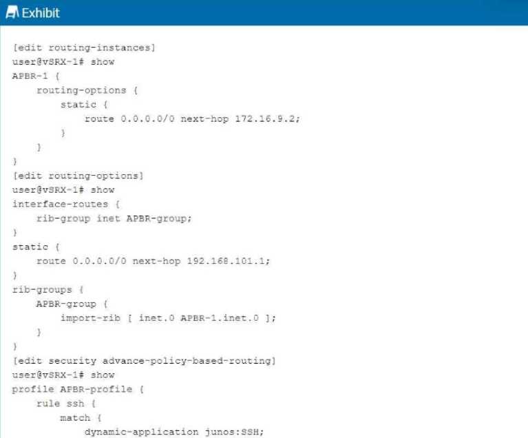
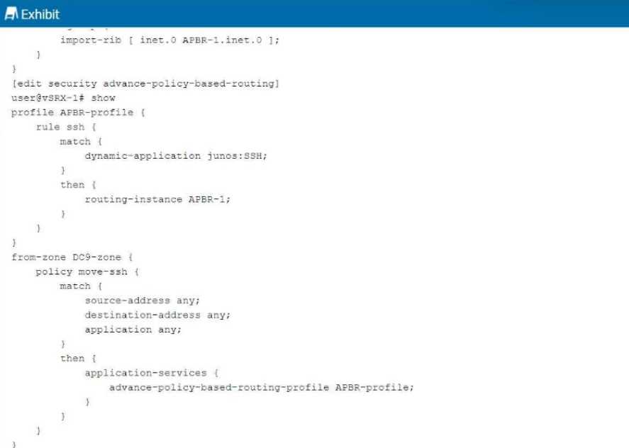
You are having problems configuring advanced policy-based routing.
What should you do to solve the problem?
- A. Apply a policy to the APBR RIB group to only allow the exact routes you need.
- B. Change the routing instance to a forwarding instance.
- C. Change the routing instance to a virtual router instance.
- D. Remove the default static route from the main instance configuration.
Answer:
B
Question 8
Exhibit: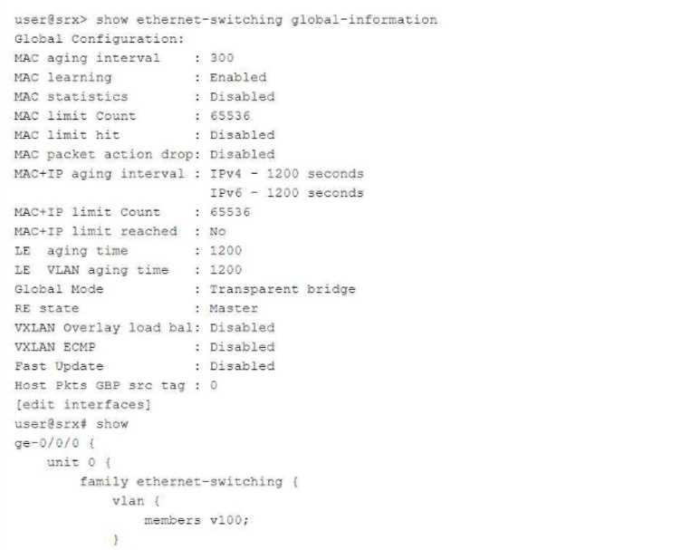
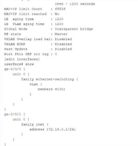
In which mode is the SRX Series device?
- A. Packet
- B. Ethernet switching
- C. Mixed
- D. Transparent
Answer:
C
Question 9
You configure two Ethernet interfaces on your SRX Series device as Layer 2 interfaces and add them
to the same VLAN. The SRX is using the default L2-learning setting. You do not add the interfaces to a
security zone.
Which two statements are true in this scenario? (Choose two.)
- A. You are unable to apply stateful security features to traffic that is switched between the two interfaces.
- B. You are able to apply stateful security features to traffic that enters and exits the VLAN.
- C. The interfaces will not forward traffic by default.
- D. You cannot add Layer 2 interfaces to a security zone.
Answer:
AC
Explanation:
When Ethernet interfaces are configured as Layer 2 and added to the same VLAN without being
assigned to a security zone, they will not forward traffic by default. Additionally, because they are
operating in a pure Layer 2 switching mode, they lack the capability to enforce stateful security
policies. For further details, refer to Juniper Ethernet Switching Layer 2 Documentation.
Explanation of Answer A (Unable to Apply Stateful Security Features):
When two interfaces are configured as Layer 2 interfaces and belong to the same VLAN but are not
assigned to any security zone, traffic switched between them is handled purely at Layer 2. Stateful
security features, such as firewall policies, are applied at Layer 3, so traffic between these interfaces
will not undergo any stateful inspection or firewalling by default.
Explanation of Answer C (Interfaces Will Not Forward Traffic):
In Junos, Layer 2 interfaces must be added to a security zone to allow traffic forwarding. Since the
interfaces in this scenario are not part of a security zone, they will not forward traffic by default until
assigned to a zone. This is a security measure to prevent unintended forwarding of traffic.
Juniper Security Reference:
Layer 2 Interface Configuration: Layer 2 interfaces must be properly assigned to security zones to
enable traffic forwarding and apply security policies. Reference: Juniper Networks Layer 2 Interface
Documentation.
Question 10
Which two statements are true about the procedures the Junos security device uses when handling
traffic destined for the device itself? (Choose two.)
- A. If the received packet is addressed to the ingress interface, then the device first performs a security policy evaluation for the junos-host zone.
- B. If the received packet is destined for an interface other than the ingress interface, then the device performs a security policy evaluation for the junos-host zone.
- C. If the received packet is addressed to the ingress interface, then the device first examines the host- inbound-traffic configuration for the ingress interface and zone.
- D. If the received packet is destined for an interface other than the ingress interface, then the device performs a security policy evaluation based on the ingress and egress zone.
Answer:
BC
Explanation:
When handling traffic that is destined for itself, the SRX examines the host-inbound-traffic
configuration for the ingress interface and the associated security zone. It evaluates whether the
traffic should be allowed based on this configuration. Traffic not addressed to the ingress interface is
handled based on security policies within the junos-host zone, which applies to traffic directed to the
SRX itself. For more details, refer to Juniper Host Inbound Traffic Documentation.
When handling traffic that is destined for the SRX device itself (also known as host-bound traffic), the
SRX follows a specific process to evaluate the traffic and apply the appropriate security policies. The
junos-host zone is a special security zone used for managing traffic destined for the device itself, such
as management traffic (SSH, SNMP, etc.).
Explanation of Answer B (Packet to a Different Interface):
If the packet is destined for an interface other than the ingress interface, the SRX performs a security
policy evaluation specifically for the junos-host zone. This ensures that management or host-bound
traffic is evaluated according to the security policies defined for that zone.
Explanation of Answer C (Packet to the Ingress Interface):
If the packet is addressed to the ingress interface, the device first checks the host-inbound-traffic
configuration for the ingress interface and zone. This configuration determines whether certain types
of traffic (such as SSH, HTTP, etc.) are allowed to reach the device on that specific interface.
Step-by-Step Handling of Host-Bound Traffic:
Host-Inbound Traffic: Define which services are allowed to the SRX device itself:
bash
set security zones security-zone <zone-name> host-inbound-traffic system-services ssh
Security Policy for junos-host: Ensure policies are defined for managing traffic destined for the SRX
device:
bash
set security policies from-zone <zone-name> to-zone junos-host policy allow-ssh match source-
address any
set security policies from-zone <zone-name> to-zone junos-host policy allow-ssh match destination-
address any
Juniper Security Reference:
Junos-Host Zone: This special zone handles traffic destined for the SRX device, including
management traffic. Security policies must be configured to allow this traffic. Reference: Juniper
Networks Host-Inbound Traffic Documentation.
Question 11
Exhibit: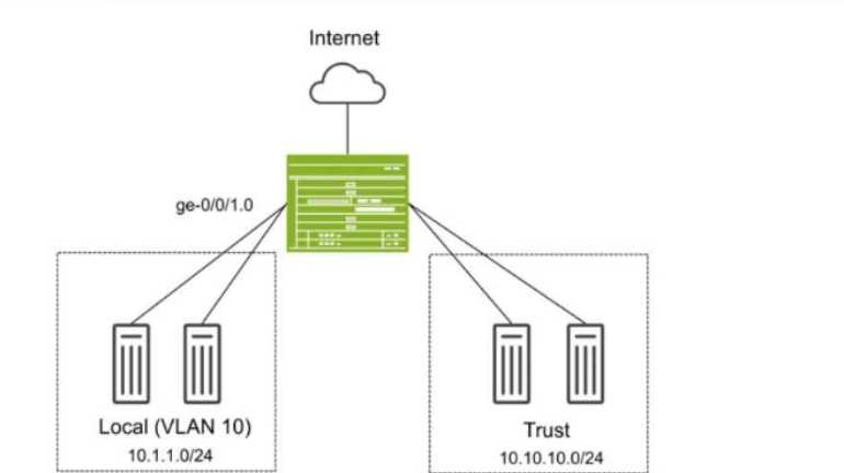
You have deployed an SRX Series device as shown in the exhibit. The devices in the Local zone have
recently been added, but their SRX interfaces have not been configured. You must configure the SRX
to meet the following requirements:
Devices in the 10.1.1.0/24 network can communicate with other devices in the same network but
not with other networks or the SRX.
You must be able to apply security policies to traffic flows between devices in the Local zone.
Which three configuration elements will be required as part of your configuration? (Choose three.)
- A. set security zones security-zone Local interfaces ge-0/0/1.0
- B. set interfaces ge-0/0/1 unit 0 family ethernet-switching vlan-members 10
- C. set protocols l2-learning global-mode switching
- D. set protocols l2-learning global-mode transparent-bridge
- E. set security zones security-zone Local interfaces irb.10
Answer:
ABD
Explanation:
In this scenario, we need to configure the SRX Series device so that devices in the Local zone (VLAN
10, 10.1.1.0/24 network) can communicate with each other but not with other networks or the SRX
itself. Additionally, you must be able to apply security policies to traffic flows between the devices in
the Local zone.
Explanation of Answer A (Assigning Interface to Security Zone):
You need to assign the interface ge-0/0/1.0 to the Local security zone. This is crucial because the SRX
only applies security policies to interfaces assigned to security zones. Without this, traffic between
devices in the Local zone won't be processed by security policies.
Configuration:
set security zones security-zone Local interfaces ge-0/0/1.0
Explanation of Answer B (Configuring Ethernet-Switching for VLAN 10):
Since we are using Layer 2 switching between devices in VLAN 10, we need to configure the interface
to operate in Ethernet switching mode and assign it to VLAN 10.
Configuration:
set interfaces ge-0/0/1 unit 0 family ethernet-switching vlan-members 10
Explanation of Answer D (Transparent Bridging Mode for Layer 2):
The global mode for Layer 2 switching on the SRX device must be set to transparent-bridge. This
ensures that the SRX operates in Layer 2 mode and can switch traffic between devices without
routing.
Configuration:
set protocols l2-learning global-mode transparent-bridge
Summary:
Interface Assignment: Interface ge-0/0/1.0 is assigned to the Local zone to allow policy enforcement.
Ethernet-Switching: The interface is configured for Layer 2 Ethernet switching in VLAN 10.
Transparent Bridging: The SRX is configured in Layer 2 transparent-bridge mode for switching
between devices.
Juniper Security Reference:
Layer 2 Bridging and Switching Overview: This mode allows the SRX to act as a Layer 2 switch for
forwarding traffic between VLAN members without routing. Reference: Juniper Transparent Bridging
Documentation.
Question 12
Exhibit: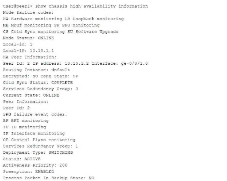
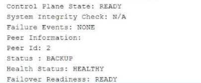
Referring to the exhibit, which statement is true?
- A. SRG1 is configured in hybrid mode.
- B. The ICL is encrypted.
- C. If SRG1 moves to peer 2, peer 1 will drop packets sent to the SRG1 interfaces.
- D. If SRG1 moves to peer 2, peer 1 will forward packets sent to the SRG1 interfaces.
Answer:
D
Explanation:
The exhibit describes a Chassis Cluster configuration with high availability (HA) settings. The key
information is related to Service Redundancy Group 1 (SRG1) and its failover behavior between the
two peers.
Explanation of Answer D (Packet Forwarding after Failover):
In a typical SRX HA setup with active/backup configuration, if the SRG1 group moves to peer 2 (the
backup), peer 1 (previously the active node) will forward packets to peer 2 instead of dropping them.
This ensures smooth failover and seamless continuation of services without packet loss.
This behavior is part of the active/backup failover process in SRX chassis clusters, where the standby
peer takes over traffic processing without disruption.
Juniper Security Reference:
Chassis Cluster Failover Behavior: When a service redundancy group fails over to the backup peer,
the previously active peer forwards traffic to the new active node. Reference: Juniper Chassis Cluster
Documentation.
Question 13
You are asked to create multiple virtual routers using a single SRX Series device. You must ensure that
each virtual router maintains a unique copy of the routing protocol daemon (RPD) process.
Which solution will accomplish this task?
- A. Secure wire
- B. Tenant system
- C. Transparent mode
- D. Logical system
Answer:
D
Explanation:
Logical systems on SRX Series devices allow the creation of separate virtual routers, each with its
unique RPD process. This segmentation ensures that routing and security policies are isolated across
different logical systems, effectively acting like independent routers within a single SRX device. For
further information, see Juniper Logical Systems Documentation.
To create multiple virtual routers on a single SRX Series device, each with its own unique copy of the
routing protocol daemon (RPD) process, you need to use logical systems. Logical systems allow for
the segmentation of an SRX device into multiple virtual routers, each with independent
configurations, including routing instances, policies, and protocol daemons.
Explanation of Answer D (Logical System):
A logical system on an SRX device enables you to create multiple virtual instances of the SRX, each
operating independently with its own control plane and routing processes. Each logical system gets a
separate copy of the RPD process, ensuring complete isolation between virtual routers.
This is the correct solution when you need separate routing instances with their own RPD processes
on the same physical device.
Configuration Example:
bash
set logical-systems <logical-system-name> interfaces ge-0/0/0 unit 0
set logical-systems <logical-system-name> routing-options static route 0.0.0.0/0 next-hop
192.168.1.1
Juniper Security Reference:
Logical Systems Overview: Logical systems allow for the creation of multiple virtual instances within a
single SRX device, each with its own configuration and control plane. Reference: Juniper Logical
Systems Documentation.
Question 14
Click the Exhibit button.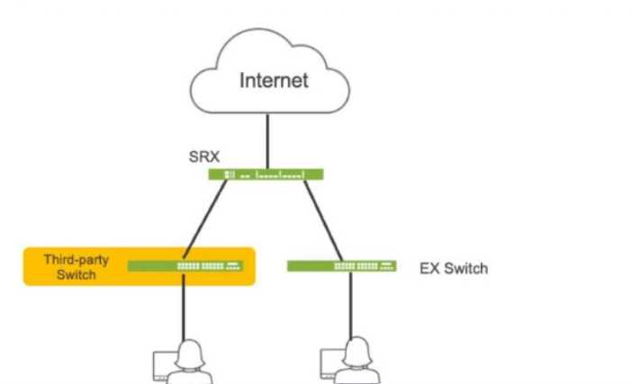
Referring to the exhibit, which three actions do you need to take to isolate the hosts at the switch
port level if they become infected with malware? (Choose three.)
- A. Enroll the SRX Series device with Juniper ATP Cloud.
- B. Use a third-party connector.
- C. Deploy Security Director with Policy Enforcer.
- D. Configure AppTrack on the SRX Series device.
- E. Deploy Juniper Secure Analytics.
Answer:
ABC
Explanation:
A. Enroll the SRX Series device with Juniper ATP Cloud. This is essential for the SRX to receive threat
intelligence from ATP Cloud, enabling it to identify infected hosts and take action.
B. Use a third-party connector. In this specific scenario, a third-party connector is required to
integrate the SRX with the third-party switch. While Juniper has native integration for its EX switches,
a connector is necessary to communicate with and manage the third-party switch.
C. Deploy Security Director with Policy Enforcer. Security Director orchestrates the automated
response, and Policy Enforcer translates the policies into device-specific commands for the SRX and
the third-party switch (via the connector).
Question 15
You want to deploy two vSRX instances in different public cloud providers to provide redundant
security services for your network. Layer 2 connectivity between the two vSRX instances is not
possible.
What would you configure on the vSRX instances to accomplish this task?
- A. Chassis cluster
- B. Secure wire
- C. Multinode HA
- D. Virtual chassis
Answer:
C