Juniper jn0-480 practice test
Data Center, Specialist
Question 1
Which statement is true when onboarding a Juniper Networks device using a Juniper Apstra ZTP
server?
- A. The Device Key lo be used can be set In the dhcpd.conf file on the ZTP server.
- B. The State can be set In the ztp.Json file on the ZTP server.
- C. The Management IP address cannot be predetermined.
- D. The Hostname will be the serial-number of the device.
Answer:
B
Explanation:
The ztp.Json file on the Apstra ZTP server contains the configuration parameters for each device that
is onboarded using ZTP. One of the parameters is the State, which can be one of the following
values: init, ready, in_progress, done, error, or disabled. The State indicates the current status of the
device in the ZTP process. For example, if the State is ready, it means that the device is ready to be
onboarded by the Apstra ZTP server. If the State is done, it means that the device has completed the
ZTP process and is managed by the Apstra server. The State can be manually set or changed in the
ztp.Json file to control the behavior of the device during ZTP. For more information, see
Apstra ZTP
Configuration File
. Reference:
Apstra ZTP Configuration File
Apstra ZTP Introduction
Configure Apstra ZTP
Question 2
You have designed your fabric in Juniper Apstra prior to deploying the network devices.
Which Apstra element in the Staged tab would be used to assist the team that is installing and
cabling the devices?
- A. Connectivity Templates
- B. Virtual Networks table
- C. Managed Devices list
- D. Links table
Answer:
D
Explanation:
The Links table in the Staged tab shows the physical connections between the devices in the fabric. It
provides information such as the source and destination device names, hostnames, serial numbers,
roles, interfaces, and link status. The Links table can be used to assist the team that is installing and
cabling the devices by verifying that the devices are connected correctly and that the links are
operational. The Links table can also be used to troubleshoot any connectivity issues that may arise
during the installation process. For more information, see
Links (Staged)
. Reference:
Links (Staged)
Topology (Staged)
Staged
Question 3
When editing a device configuration to install some manual changes, which procedure should be
followed?
- A. Edit the configuration on the device directly by the CLI; the changes will automatically be adjusted in the Juniper Apstra configuration
- B. Edit the pristine configuration of the device.
- C. Add a persistent change to a device configuration with a configlet.
- D. Delete the device from the Juniper Apstra system, change the configuration, then re-import the device.
Answer:
C
Explanation:
A configlet is a small piece of configuration that can be applied to a device or a group of devices to
make persistent changes that are not overwritten by Apstra. Configlets can be used to install manual
changes that are not part of the Apstra rendered configuration, such as custom commands, scripts, or
features.
Configlets can be created, edited, and deleted from the Apstra GUI or CLI12
. Reference:
Configlets Overview
Configlets User Guide
Question 4
In Juniper Apstr
a. which statement is correct?
- A. VMware anomaly detection is on by default.
- B. VMware anomaly detection requires a vCenter server configured under External Systems
- C. VMware anomaly detection requires a VMware hypervisor with exports enabled.
- D. VMware anomaly detection requires an Apstra server running on VMware.
Answer:
B
Explanation:
VMware anomaly detection is a feature of Apstra that provides visibility and validation of the virtual
network settings and the physical network settings in a VMware vSphere environment. To enable this
feature, Apstra requires a connection to a vCenter server that manages the ESX/ESXi hosts and the
VMs connected to the Apstra-managed leaf switches. The vCenter server must be configured under
External Systems in the Apstra web interface, and the vCenter integration must be staged and
committed in the blueprint. This allows Apstra to collect information about VMs, ESX/ESXi hosts, port
groups, and VDS, and to flag any inconsistencies or mismatches that might affect VM connectivity.
The other options are incorrect because:
VMware anomaly detection is not on by default. It must be enabled by configuring a vCenter server
under External Systems and adding a virtual infra to the blueprint.
VMware anomaly detection does not require a VMware hypervisor with exports enabled. It only
requires LLDP transmit to be enabled on the VMware distributed virtual switch to associate host
interfaces with leaf interfaces.
VMware anomaly detection does not require an Apstra server running on VMware. It can run on any
supported platform, such as Linux, Windows, or Docker. Reference:
VMware vCenter/vSphere Virtual Infra
Anomalies (Service)
A Better Experience: VMware + Juniper Apstra
Question 5
Exhibit.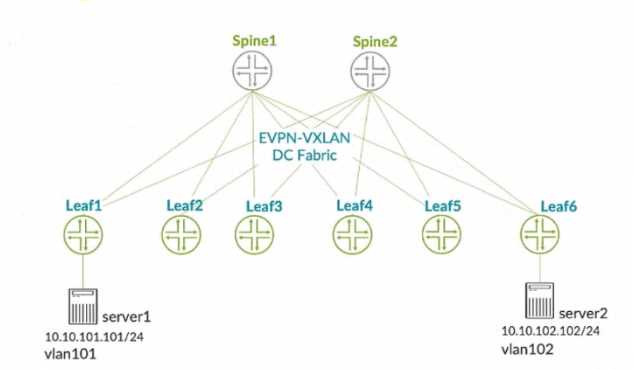
You connect two single-homed servers using Juniper Apstra as shown in the exhibit. You are using the
ERB design blueprint with two virtual networks in a common routing zone.
In this scenario, which two types of VXLAN tunnels will be automatically created by the EVPN control
plane? (Choose two.)
- A. EVPN signaled route Type-8 VXLAN tunnels
- B. EVPN signaled route Type-3 VXLAN tunnels
- C. EVPN signaled route Type-6 VXLAN tunnels
- D. EVPN signaled route Type-2 VXLAN tunnels
Answer:
BD
Explanation:
According to the Juniper documentation1
, EVPN route Type-3 is used to advertise the IP address of
the VTEP and the VNIs that it supports. This allows the VTEPs to discover each other and form VXLAN
tunnels for the VNIs that they have in common. EVPN route Type-2 is used to advertise the MAC and
IP addresses of the hosts connected to the VTEPs. This allows the VTEPs to learn the MAC-to-IP
bindings and the MAC-to-VTEP mappings for the hosts in the same VNI. Therefore, these two types
of VXLAN tunnels will be automatically created by the EVPN control plane when using Juniper Apstra
with the ERB design blueprint and two virtual networks in a common routing
zone. Reference:
Example: Configure an EVPN-VXLAN Centrally-Routed Bridging Fabric
Question 6
In the Juniper Apstra design phase, which object dictates port count, port speed, and how the ports
would be used?
- A. logical devices
- B. rack type
- C. network devices
- D. interface map
Answer:
D
Explanation:
Interface maps are objects that map interfaces between logical devices and physical hardware
devices in the Juniper Apstra design phase. They dictate port count, port speed, and how the ports
would be used for achieving the intended network configuration rendering. Interface maps also
allow you to select device ports, transformations, and interfaces, provision breakout ports, and
disable unused ports. For more information, see
Interface Maps (Datacenter Design)
. Reference:
Interface Maps (Datacenter Design)
Design
Interface Maps Introduction
Question 7
You want to keep virtual networks isolated from each other within the Juniper Apstra system.
In this scenario, what are three ways to accomplish this task? (Choose three.)
- A. Disable IPv4 connectivity when creating the virtual network within the same Routing Zone.
- B. Enable Security Policy for virtual networks in the same Routing Zone.
- C. Disable Route Target exports when creating the Routing Zones.
- D. Use Connectivity Templates to block access within the same Routing Zone.
- E. Put each network in different Routing Zones.
Answer:
BDE
Explanation:
To keep virtual networks isolated from each other within the Juniper Apstra system, you can use one
or more of the following methods:
Enable Security Policy for virtual networks in the same Routing Zone. This allows you to define rules
that control the traffic flow between different virtual networks within the same routing zone. You can
specify the source and destination virtual networks, the protocol, the port, and the action (allow or
deny) for each rule.
The security policy is applied on the ingress interface of the leaf devices1
.
Use Connectivity Templates to block access within the same Routing Zone. This allows you to
customize the connectivity between different racks within the same routing zone. You can create
templates that define the link type, the routing protocol, and the access control list (ACL) for each
rack pair.
The ACL can be used to filter the traffic based on the source and destination IP addresses,
the protocol, and the port2
.
Put each network in different Routing Zones. This allows you to create logical boundaries between
different virtual networks based on the route target (RT) values. A routing zone is a collection of
virtual networks that share the same RT for importing and exporting routes.
Virtual networks in
different routing zones do not exchange routes with each other, unless you configure remote EVPN
gateways to connect them3
. Reference:
Security Policy
Connectivity Templates
Routing Zones
Question 8
Exhibit.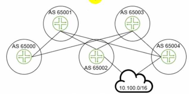
The 10.100.0.0/16 route is being advertised into your BGP IP fabric. ECMP load balancing has been
properly enabled on all devices
In this scenario, how many routes will the leaf device in AS 65000 receive for the 10.100.0.0/16
prefix?
- A. 3
- B. 1
- C. 2
- D. 4
Answer:
A
Explanation:
The leaf device in AS 65000 will receive three routes for the 10.100.0.0/16 prefix, one from each
spine device in AS 65001, AS 65002, and AS 65003. Since ECMP load balancing is enabled, the leaf
device will install all three routes in its routing table and distribute the traffic among them. The other
options are incorrect because:
B) 1 is wrong because the leaf device will not receive only one route for the prefix. It will receive
multiple routes from different spine devices and use ECMP to load balance among them.
C) 2 is wrong because the leaf device will not receive only two routes for the prefix. It will receive
three routes from three spine devices, as explained above.
D) 4 is wrong because the leaf device will not receive four routes for the prefix. It will receive three
routes from three spine devices, as explained above. The fourth spine device in AS 65004 is not
directly connected to the leaf device and will not advertise the prefix to it. Reference:
IP Fabric Underlay Network Design and Implementation
BGP Multipath load sharing iBGP and eBGP
ECMP Load Balancing
Question 9
Using the Juniper Apstra multitenancy capabilities, which approach will allow a tenant to
interconnect two different routing zones?
- A. Interconnection is the default behavior.
- B. Use interconnection through the fabric spine nodes.
- C. Interconnection cannot be enabled.
- D. Use interconnection through an external gateway.
Answer:
D
Explanation:
According to the Juniper documentation1
, a routing zone is an L3 domain, the unit of tenancy in
multi-tenant networks. You create routing zones for tenants to isolate their IP traffic from one
another, thus enabling tenants to re-use IP subnets. In addition to being in its own VRF, each routing
zone can be assigned its own DHCP relay server and external system connections. You can create one
or more virtual networks within a routing zone, which means a tenant can stretch its L2 applications
across multiple racks within its routing zone. For virtual networks with Layer 3 SVI, the SVI is
associated with a Virtual Routing and Forwarding (VRF) instance for each routing zone isolating the
virtual network SVI from other virtual network SVIs in other routing zones. If you’re using multiple
routing zones, external system connections must be from leaf switches in the fabric. Routing
between routing zones must be accomplished with external systems. Therefore, the correct answer is
D. Use interconnection through an external gateway. Reference:
Routing Zones
Question 10
Exhibit.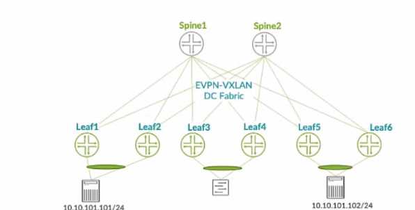
In the EVPN-VXLAN data center fabric bridged overlay architecture shown in the exhibit, the servers
are connected to Lead and Leat6 using the same virtual network identifier (VNI).
Which two statements are correct in this scenario? (Choose two.)
- A. The underlay must use IRB interfaces.
- B. The underlay must be provisioned with PIMv2.
- C. Loopback IPv4 addresses must be advertised into the EBGP underlay from leaf and spine devices.
- D. The underlay EBGP peering’s must be established between leaf and spine devices.
Answer:
CD
Explanation:
In the EVPN-VXLAN data center fabric bridged overlay architecture shown in the exhibit, the servers
are connected to Leaf1 and Leaf6 using the same virtual network identifier (VNI). This means that the
servers belong to the same Layer 2 domain and can communicate with each other using VXLAN
tunnels across the fabric. The underlay network provides the IP connectivity between the leaf and
spine devices, and it uses EBGP as the routing protocol. Therefore, the following two statements are
correct in this scenario:
Loopback IPv4 addresses must be advertised into the EBGP underlay from leaf and spine devices.
This is because the loopback addresses are used as the source and destination IP addresses for the
VXLAN tunnels, and they must be reachable by all the devices in the fabric. The loopback addresses
are also used as the router IDs and the BGP peer addresses for the EBGP sessions.
The underlay EBGP peering’s must be established between leaf and spine devices. This is because
the EBGP sessions are used to exchange the underlay routing information and the EVPN routes for
the overlay network. The EBGP sessions are established using the loopback addresses of the devices,
and they follow a spine-and-leaf topology, where each leaf device peers with all the spine devices,
and each spine device peers with all the leaf devices.
The following two statements are incorrect in this scenario:
The underlay must use IRB interfaces. This is not true, because the underlay network does not
provide any Layer 3 gateway functionality for the overlay network. The IRB interfaces are used to
provide inter-VXLAN routing within the fabric, which is not the case in the bridged overlay
architecture. The IRB interfaces are used in the edge-routed bridging (ERB) or the centrally-routed
bridging (CRB) architectures, which are different from the bridged overlay architecture.
The underlay must be provisioned with PIMv2. This is not true, because the underlay network does
not use multicast for the VXLAN tunnels. The VXLAN tunnels are established using EVPN, which uses
BGP to distribute the MAC and IP addresses of the end hosts and the VTEP information of the
devices. EVPN eliminates the need for multicast in the underlay network, and it provides optimal
forwarding and fast convergence for the overlay network.
Reference:
Exploring EVPN-VXLAN Overlay Architectures – Bridged Overlay
EVPN LAGs in EVPN-VXLAN Reference Architectures
EVPN-VXLAN Configuration Guide
Question 11
You are receiving cable, interface, and BGP anomalies from several devices within the data center
fabric. In Juniper Apstr
a. how would you troubleshoot these types of errors?
- A. In the Ul, go to Time Voyager and revert to the last working version.
- B. In the Ul, access the console to the devices and review the interface states.
- C. In the Ul, go to Devices and confirm that agent connectivity is fine.
- D. In the Ul, verify device connectivity by consulting the cable map.
Answer:
D
Explanation:
The cable map is a graphical representation of the physical connections between the devices in the
data center fabric. It shows the status of the cables, interfaces, and BGP sessions for each device. You
can use the cable map to identify and troubleshoot any cable, interface, or BGP anomalies that may
occur in the fabric.
You can also filter the cable map by device name, device type, device role, device
state, cable state, interface state, or BGP state12
. Reference:
Cable Map Overview
Cable Map User Guide
Question 12
Exhibit.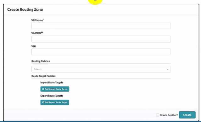
Referring to the exhibit, what is the minimum information you must add to create a new routing
zone?
- A. VRF Name only
- B. VRF Name and Routing policies
- C. VRF Name, VLAN ID. And VNI
- D. VRF Name, VLAN ID, VNI, Routing Policies
Answer:
C
Explanation:
To create a new routing zone, you must specify the VRF Name, VLAN ID, and VNI for the routing zone.
These are the mandatory fields in the user interface shown in the exhibit. The VRF Name is the name
of the L3 domain that isolates the IP traffic of the routing zone from other routing zones. The VLAN ID
is the identifier for the VLAN tagged Layer 3 links on external connections. The VNI is the VxLAN
Network Identifier associated with the routing zone. The Routing Policies are optional fields that
allow you to configure import and export route targets for the routing zone. These are only
applicable for EVPN routing zones, which use MP-EBGP as the overlay control protocol. The other
options are incorrect because:
A) VRF Name only is wrong because you also need to specify the VLAN ID and VNI for the routing
zone.
B) VRF Name and Routing policies is wrong because you also need to specify the VLAN ID and VNI for
the routing zone. Routing policies are optional and only relevant for EVPN routing zones.
D) VRF Name, VLAN ID, VNI, Routing Policies is wrong because Routing Policies are optional and not
required to create a new routing zone. Reference:
Routing Zones (Virtual)
Data Center Automation Using Juniper Apstra
Question 13
Which two statements are correct about Time Voyager? {Choose two.)
- A. Time Voyager retains all of the blueprint revisions from the last Juniper Apstra backup.
- B. Time Voyager retains the five most recent blueprint commits.
- C. Time Voyager retains the last ten blueprint commits.
- D. Time Voyager retains up to twenty-five saved revisions.
Answer:
BD
Explanation:
Time Voyager is a feature of Juniper Apstra that allows you to restore previous revisions of a
blueprint, which is a logical representation of your network design and configuration. Time Voyager
automatically saves the five most recent blueprint commits, which are the changes that you apply to
the network. You can also manually save up to twenty-five revisions by keeping them, which
prevents them from being overwritten by new commits. Therefore, the correct answer is B and D.
Time Voyager retains the five most recent blueprint commits and Time Voyager retains up to twenty-
five saved revisions. Reference:
Time Voyager | Apstra 4.1 | Juniper Networks
,
Time Voyager
Introduction | Apstra 4.2 | Juniper Networks
,
Juniper Apstra at a Glance | Flyer
Question 14
In the Juniper Apstra Ul. which three resources are assigned under the Resources menu? (Choose
three.)
- A. VTEP pools
- B. ASN pools
- C. VNI pools
- D. logical device pools
- E. IP address pools
Answer:
BCE
Explanation:
In the Juniper Apstra UI, the Resources menu allows you to create and manage global and local
resources that are used for various elements of the network design and configuration. The Resources
menu includes the following three types of resources that can be assigned to the network devices
and virtual networks:
ASN pools: These are pools of autonomous system numbers (ASNs) that are used for the underlay
routing protocol (EBGP) between the leaf and spine devices. You can create ASN pools with either 2-
byte or 4-byte ASNs, and assign them to the logical devices in the blueprint.
VNI pools: These are pools of virtual network identifiers (VNIs) that are used for the overlay network
(VXLAN) between the end hosts. You can create VNI pools with a range of VNIs, and assign them to
the virtual networks in the blueprint.
IP address pools: These are pools of IPv4 or IPv6 addresses that are used for various purposes in the
network, such as the loopback addresses for the devices, the IP prefixes for the virtual networks, the
host IP addresses for the end hosts, and the gateway IP addresses for the IRB interfaces. You can
create IP address pools with a range of IP addresses, and assign them to the logical devices and
virtual networks in the blueprint.
The following two types of resources are not assigned under the Resources menu:
VTEP pools: These are not resources that can be created or assigned by the user. VTEPs are VXLAN
tunnel endpoints that are automatically generated by the Apstra server based on the loopback IP
addresses of the devices. VTEPs are used as the source and destination IP addresses for the VXLAN
tunnels in the overlay network.
Logical device pools: These are not resources that can be created or assigned by the user. Logical
device pools are groups of logical devices that share the same role, interface map, and resource
assignments in the blueprint. Logical device pools are used to simplify the network design and
configuration by applying the same settings to multiple devices.
Reference:
Resources Introduction
ASN Pools (Resources)
VNI Pools (Resources)
IP Address Pools (Resources)
Question 15
In Juniper Apstr
a. which three modes are available for devices? (Choose three.)
- A. Deploy
- B. Active
- C. Stopped
- D. Drain
- E. Ready
Answer:
ADE
Explanation:
Juniper Apstra supports three deploy modes for devices: Deploy, Drain, and Ready.
These modes
determine the configuration and state of the devices in the data center fabric12
.
Deploy: This mode applies the full Apstra-rendered configuration to the device, according to the
Apstra Reference Design.
The device state becomes IS-ACTIVE and the device is ready to carry traffic
in the fabric12
.
Drain: This mode adds a “drain” configuration to the device, which prevents any new traffic from
entering the device.
The device state becomes IS-READY and the device is prepared for maintenance
or decommissioning12
.
Ready: This mode removes the Apstra-rendered configuration from the device, leaving only the basic
configuration such as device hostname, interface descriptions, and port speed/breakout.
The device
state becomes IS-READY and the device is not part of the fabric12
. Reference:
Device Configuration Lifecycle
Set Deploy Mode (Datacenter)