Juniper jn0-351 practice test
Enterprise Routing and Switching, Specialist (JNCIS-ENT)
Question 1
Exhibit.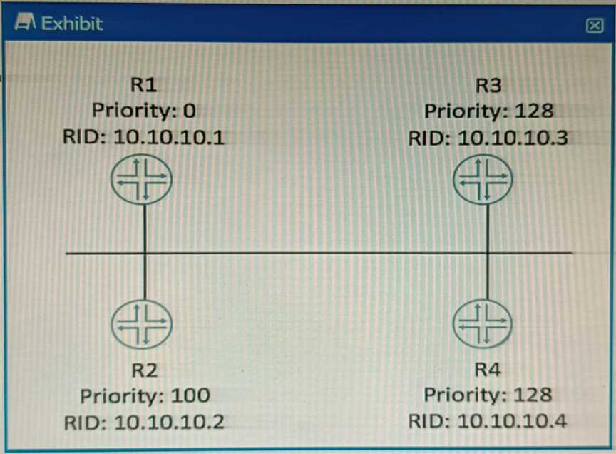
Which router will become the OSPF BDR if all routers are powered on at the same time?
- A. R4
- B. R1
- C. R3
- D. R2
Answer:
A
Explanation:
OSPF DR/BDR election is a process that occurs on multi-access data links. It is intended to select two
OSPF nodes: one to be acting as the Designated Router (DR), and another to be acting as the Backup
Designated Router (BDR).
The DR and BDR are responsible for generating network LSAs for the multi-
access network and synchronizing the LSDB with other routers on the same network1
.
The DR/BDR election is based on two criteria: the OSPF priority and the router ID. The OSPF priority
is a value between 0 and 255 that can be configured on each interface participating in OSPF. The
default priority is 1. A priority of 0 means that the router will not participate in the election and will
never become a DR or BDR. The router with the highest priority will become the DR, and the router
with the second highest priority will become the BDR. If there is a tie in priority, then the router ID is
used as a tie-breaker. The router ID is a 32-bit number that uniquely identifies each router in an OSPF
domain.
It can be manually configured or automatically derived from the highest IP address on a
loopback interface or any active interface2
.
In this scenario, all routers have the same priority of 1, so the router ID will determine the outcome
of the election. The router IDs are shown in the exhibit as RID values. The highest RID belongs to R4
(10.10.10.4), so R4 will become the DR. The second highest RID belongs to R3 (10.10.10.3), so R3 will
become the BDR.
Reference:
:
OSPF DR/BDR Election: Process, Configuration, and Tuning 2
:
OSPF Designated Router (DR) and
Backup Designated Router (BDR)
Question 2
Exhibit.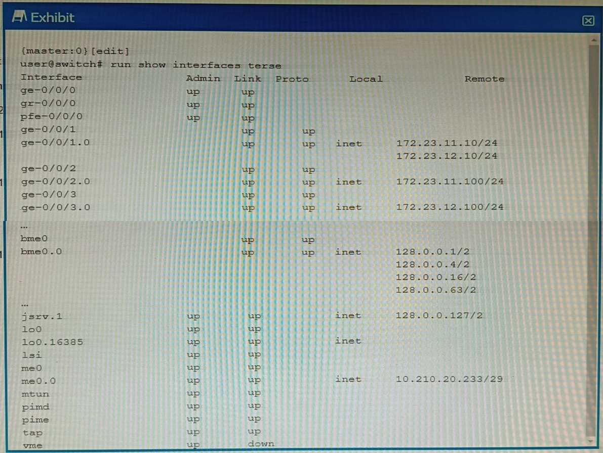
What is the management IP address of the device shown in the exhibit?
- A. 10.210.20.233
- B. 172.23.12.100
- C. 128.0.0.1
- D. 172.23.11.10
Answer:
B
Explanation:
The management IP address of a device is the IP address that is used to access the device for
configuration and monitoring purposes. It is usually assigned to a dedicated management interface
that is separate from the data interfaces. The management interface can be accessed via SSH, Telnet,
HTTP, or other protocols.
In the exhibit, the list of interfaces and their statuses shows that the management interface is me0.
This interface has an admin status of up, a protocol status of inet, a local address of
172.23.12.100/24, and a remote address of unspecified. This means that the me0 interface is active,
has an IPv4 address assigned, and is not connected to another device.
Therefore, the management IP address of the device shown in the exhibit is 172.23.12.100.
Reference:
: [Management Interfaces Overview] : [Displaying Interface Status Information]
Question 3
Which three protocols support BFD? (Choose three.)
- A. RSTP
- B. BGP
- C. OSPF
- D. LACP
- F. FTP
Answer:
BCD
Explanation:
BFD is a protocol that can be used to quickly detect failures in the forwarding path between two
adjacent routers or switches. BFD can be integrated with various routing protocols and link
aggregation protocols to provide faster convergence and fault recovery.
According to the Juniper Networks documentation, the following protocols support BFD on Junos OS
devices1
:
BGP: BFD can be used to monitor the connectivity between BGP peers and trigger a session reset if a
failure is detected.
BFD can be configured for both internal and external BGP sessions, as well as for
IPv4 and IPv6 address families2
.
OSPF: BFD can be used to monitor the connectivity between OSPF neighbors and trigger a state
change if a failure is detected.
BFD can be configured for both OSPFv2 and OSPFv3 protocols, as well
as for point-to-point and broadcast network types3
.
LACP: BFD can be used to monitor the connectivity between LACP members and trigger a link state
change if a failure is detected.
BFD can be configured for both active and passive LACP modes, as
well as for static and dynamic LAGs4
.
Other protocols that support BFD on Junos OS devices are:
IS-IS: BFD can be used to monitor the connectivity between IS-IS neighbors and trigger a state change
if a failure is detected. BFD can be configured for both level 1 and level 2 IS-IS adjacencies, as well as
for point-to-point and broadcast network types.
RIP: BFD can be used to monitor the connectivity between RIP neighbors and trigger a route update
if a failure is detected. BFD can be configured for both RIP version 1 and version 2 protocols, as well
as for IPv4 and IPv6 address families.
VRRP: BFD can be used to monitor the connectivity between VRRP routers and trigger a priority
change if a failure is detected. BFD can be configured for both VRRP version 2 and version 3
protocols, as well as for IPv4 and IPv6 address families.
The protocols that do not support BFD on Junos OS devices are:
RSTP: RSTP is a spanning tree protocol that provides loop prevention and rapid convergence in layer 2
networks. RSTP does not use BFD to detect link failures, but relies on its own hello mechanism that
sends BPDU packets every 2 seconds by default.
FTP: FTP is an application layer protocol that is used to transfer files between hosts over a TCP
connection. FTP does not use BFD to detect connection failures, but relies on TCP’s own
retransmission and timeout mechanisms.
Reference:
1: [Configuring Bidirectional Forwarding Detection] 2: [Configuring Bidirectional Forwarding
Detection for BGP] 3: [Configuring Bidirectional Forwarding Detection for OSPF] 4
: [Configuring
Bidirectional Forwarding Detection for Link Aggregation Control Protocol] : [Configuring Bidirectional
Forwarding Detection for IS-IS] : [Configuring Bidirectional Forwarding Detection for RIP] :
[Configuring Bidirectional Forwarding Detection for VRRP] : [Understanding Rapid Spanning Tree
Protocol] : [Understanding FTP]
Question 4
Exhibit.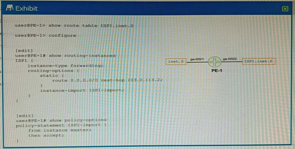
The ispi _ inet. 0 route table has currently no routes in it.
What will happen when you commit the configuration shown on the exhibit?
- A. The inet. 0 route table will be completely overwritten by the ispi . inet. 0 route table.
- B. The inet. 0 route table will be imported into the ispi . inet. 0 route table.
- C. The ISPI . inet. 0 route table will be completely overwritten by the inet. o route table.
- D. The ISPI . inet. 0 route table will be imported into the inet. 0 route table.
Answer:
B
Explanation:
The configuration shown in the exhibit is an example of a routing instance of type virtual-router.
A
routing instance is a collection of routing tables, interfaces, and routing protocol parameters that
create a separate routing domain on a Juniper device1
.
A virtual-router routing instance allows
administrators to divide a device into multiple independent virtual routers, each with its own routing
table2
.
The configuration also includes a rib-group statement, which is used to import routes from one
routing table to another. A rib-group consists of an import-rib statement, which specifies the source
routing table, and an export-rib statement, which specifies the destination routing table.
In this case, the rib-group name is inet-to-ispi, and the import-rib statement specifies inet.0 as the
source routing table. The export-rib statement specifies ispi.inet.0 as the destination routing table.
This means that the routes from inet.0 will be imported into ispi.inet.0.
Therefore, the correct answer is B. The inet.0 route table will be imported into the ispi.inet.0 route
table.
Reference:
:
Routing Instances Overview 2
:
Virtual Routing Instances
: [rib-group (Routing Options)]
Question 5
Which statement is correct about graceful Routing Engine switchover (GRES)?
- A. The PFE restarts and the kernel and interface information is lost.
- B. GRES has a helper mode and a restarting mode.
- C. When combined with NSR, routing is preserved and the new master RE does not restart rpd.
- D. With no other high availability features enabled, routing is preserved and the new master RE does not restart rpd.
Answer:
C
Explanation:
The Graceful Routing Engine Switchover (GRES) feature in Junos OS enables a router with redundant
Routing Engines to continue forwarding packets, even if one Routing Engine fails1
.
GRES preserves
interface and kernel information, ensuring that traffic is not interrupted1
.
However, GRES does not
preserve the control plane1
.
To preserve routing during a switchover, GRES must be combined with either Graceful Restart
protocol extensions or Nonstop Active Routing (NSR)1
.
When GRES is combined with NSR, nearly 75
percent of line rate worth of traffic per Packet Forwarding Engine remains uninterrupted during
GRES1
.
Any updates to the primary Routing Engine are replicated to the backup Routing Engine as
soon as they occur1
.
Therefore, when GRES is combined with NSR, routing is preserved and the new master RE does not
restart rpd1
.
Question 6
Which statement is correct about controlling the routes installed by a RIB group?
- A. An import policy is applied to the RIB group.
- B. Only routes in the last table are installed.
- C. A firewall filter must be configured to install routes in the RIB groups.
- D. An export policy is applied to the RIB group.
Answer:
A
Explanation:
A RIB group is a configuration that allows a routing protocol to install routes into multiple routing
tables in Junos OS. A RIB group consists of an import-rib statement, which specifies the source
routing table, and an export-rib statement, which specifies the destination routing table or group.
A
RIB group can also include an import-policy statement, which specifies one or more policies to
control which routes are imported into the destination routing table or group1
.
An import policy is a policy statement that defines the criteria for accepting or rejecting routes from
the source routing table. An import policy can also modify the attributes of the imported routes, such
as preference, metric, or community.
An import policy can be applied to a RIB group by using the
import-policy statement under the [edit routing-options rib-groups] hierarchy level1
.
Therefore, option A is correct, because an import policy is applied to the RIB group to control which
routes are installed in the destination routing table or group. Option B is incorrect, because all routes
in the source routing table are imported into the destination routing table or group, unless filtered by
an import policy. Option C is incorrect, because a firewall filter is not used to install routes in the RIB
groups; a firewall filter is used to filter packets based on various criteria. Option D is incorrect,
because an export policy is not applied to the RIB group; an export policy is applied to a routing
protocol to control which routes are advertised to other devices.
Reference:
:
rib-groups | Junos OS | Juniper Networks
Question 7
Exhibit.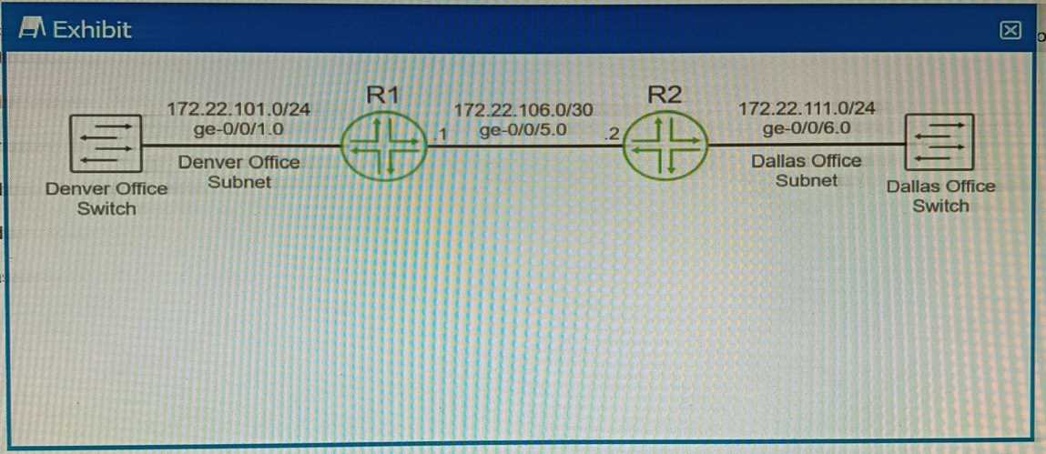
You are using OSPF to advertise the subnets that are used by the Denver and Dallas offices. The
routers that are directly connected to the Dallas and Denver subnets are not advertising the
connected subnets.
Referring to the exhibit, which two statements are correct? (Choose two.)
- A. Create static routes on the switches using the local vMX router's loopback interface for the next hop.
- B. Configure and apply a routing policy that redistributes the Dallas and Denver subnets using Type 5 LSAs.
- C. Configure and apply a routing policy that redistributes the connected Dallas and Denver subnets.
- D. Enable the passive option on the OSPF interfaces that are connected to the Dallas and Denver subnets.
Answer:
CD
Explanation:
The routers that are directly connected to the Dallas and Denver subnets are not advertising the
connected subnets.
This can be resolved by redistributing the connected subnets into OSPF1
.
Option C suggests to configure and apply a routing policy that redistributes the connected Dallas and
Denver subnets.
This is correct because redistribution allows routes from one routing protocol to be
communicated to another, and in this case, it allows the connected subnets to be advertised through
OSPF1
.
Option D suggests enabling the passive option on the OSPF interfaces that are connected to the
Dallas and Denver subnets.
This is also correct because in OSPF, a passive interface is an interface
that belongs to the OSPF router, but does not send OSPF Hello packets1
.
It’s typically used on an
interface that you don’t want to use for OSPF adjacencies, but you still want to advertise its IP
address1
. Therefore, enabling passive interface can help in advertising the Dallas and Denver
subnets.
Question 8
Exhibit.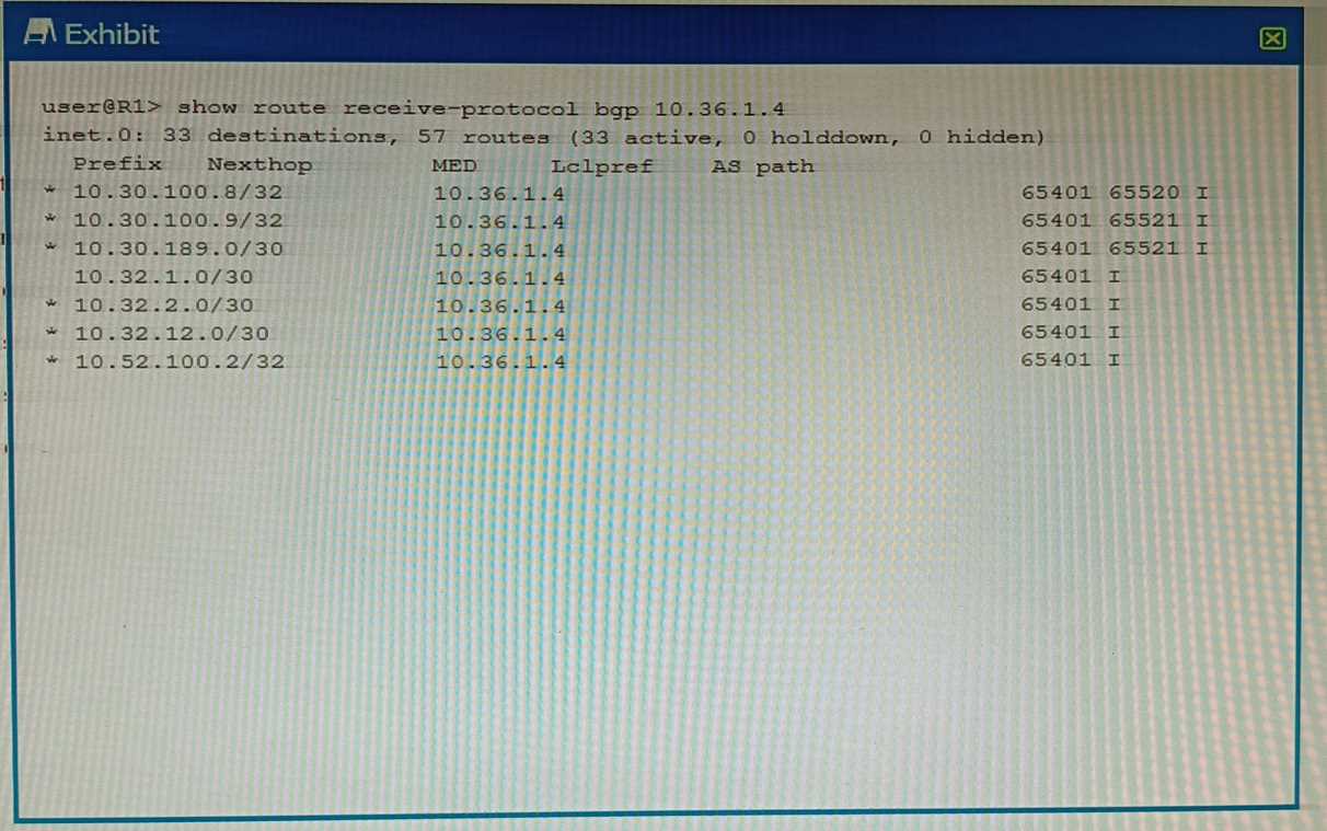
You want to verify prefix information being sent from 10.36.1.4.
Which two statements are correct about the output shown in the exhibit? (Choose two.)
- A. The routes displayed have traversed one or more autonomous systems.
- B. The output shows routes that were received prior to the application of any BGP import policies.
- C. The output shows routes that are active and rejected by an import policy.
- D. The routes displayed are being learned from an I BGP peer.
Answer:
AB
Explanation:
The output shown in the exhibit is the result of the command “show ip bgp neighbor 10.36.1.4
received-routes”, which displays all received routes (both accepted and rejected) from the specified
neighbor.
Option A is correct, because the routes displayed have traversed one or more autonomous systems.
This can be seen from the AS_PATH attribute, which shows the sequence of AS numbers that the
route has passed through. For example, the route 10.0.0.0/8 has an AS_PATH of 65001 65002, which
means that it has traversed AS 65001 and AS 65002 before reaching the local router.
Option B is correct, because the output shows routes that were received prior to the application of
any BGP import policies. This can be seen from the fact that some routes have a status code of “r”,
which means that they are rejected by an import policy. The “received-routes” keyword shows the
routes coming from a given neighbor before the inbound policy has been applied. To see the routes
after the inbound policy has been applied, the “routes” keyword should be used instead.
Option C is incorrect, because the output does not show routes that are active and rejected by an
import policy. The status code of “r” means that the route is rejected by an import policy, but it does
not mean that it is active. The status code of “>” means that the route is active and selected as the
best path. None of the routes in the output have both “>” and “r” status codes.
Option D is incorrect, because the routes displayed are not being learned from an IBGP peer. An IBGP
peer is a BGP neighbor that belongs to the same AS as the local router. The output shows that the
neighbor 10.36.1.4 has a remote AS of 65001, which is different from the local AS of 65002.
Therefore, the neighbor is an EBGP peer, not an IBGP peer.
Question 9
What is the default keepalive time for BGP?
- A. 10 seconds
- B. 60 seconds
- C. 30 seconds
- D. 90 seconds
Answer:
B
Explanation:
The default keepalive time for BGP is 60 seconds1
.
The keepalive time is the interval at which BGP
sends keepalive messages to maintain the connection with its peer1
.
If the keepalive message is not
received within the hold time, the connection is considered lost1
.
By default, the hold time is three
times the keepalive time, which is 180 seconds1
.
Question 10
Which two statements are correct about tunnels? (Choose two.)
- A. BFD cannot be used to monitor tunnels.
- B. Tunnel endpoints must have a valid route to the remote tunnel endpoint.
- C. IP-IP tunnels are stateful.
- D. Tunnels add additional overhead to packet size.
Answer:
BD
Explanation:
A tunnel is a connection between two computer networks, in which data is sent from one network to
another through an encrypted link. Tunnels are commonly used to secure data communications
between two networks or to connect two networks that use different protocols.
Option B is correct, because tunnel endpoints must have a valid route to the remote tunnel endpoint.
A tunnel endpoint is the device that initiates or terminates a tunnel connection. For a tunnel to be
established, both endpoints must be able to reach each other over the underlying network.
This
means that they must have a valid route to the IP address of the remote endpoint1
.
Option D is correct, because tunnels add additional overhead to packet size. Tunnels work by
encapsulating packets: wrapping packets inside of other packets. This means that the original packet
becomes the payload of the surrounding packet, and the surrounding packet has its own header and
trailer. The header and trailer of the surrounding packet add extra bytes to the packet size, which is
called overhead.
Overhead can reduce the efficiency and performance of a network, as it consumes
more bandwidth and processing power2
.
Option A is incorrect, because BFD can be used to monitor tunnels. BFD is a protocol that can be used
to quickly detect failures in the forwarding path between two adjacent routers or switches. BFD can
be integrated with various routing protocols and link aggregation protocols to provide faster
convergence and fault recovery. BFD can also be used to monitor the connectivity of tunnels, such as
GRE, IPsec, or MPLS.
Option C is incorrect, because IP-IP tunnels are stateless. IP-IP tunnels are a type of tunnels that use
IP as both the encapsulating and encapsulated protocol. IP-IP tunnels are simple and easy to
configure, but they do not provide any security or authentication features. IP-IP tunnels are stateless,
which means that they do not keep track of the state or status of the tunnel connection. Stateless
tunnels do not require any signaling or negotiation between the endpoints, but they also do not
provide any error detection or recovery mechanisms.
Reference:
:
What is Tunneling? | Tunneling in Networking 2
:
What Is Tunnel In Networking, Its Types, And Its
Benefits?
: [Configuring Bidirectional Forwarding Detection] : [IP-IP Tunneling]
Question 11
Which statement is correct about IP-IP tunnels?
- A. IP-IP tunnels only support encapsulating IP traffic.
- B. IP-IP tunnels only support encapsulating non-IP traffic.
- C. The TTL in the inner packet is decremented during transit to the tunnel endpoint.
- D. There are 24 bytes of overhead with IP-IP encapsulation.
Answer:
A
Explanation:
IP-IP tunnels are a type of tunnels that use IP as both the encapsulating and encapsulated protocol.
IP-IP tunnels are simple and easy to configure, but they do not provide any security or authentication
features. IP-IP tunnels only support encapsulating IP traffic, which means that the payload of the
inner packet must be an IP packet.
IP-IP tunnels cannot encapsulate non-IP traffic, such as Ethernet
frames or MPLS labels1
.
Option A is correct, because IP-IP tunnels only support encapsulating IP traffic. Option B is incorrect,
because IP-IP tunnels only support encapsulating non-IP traffic. Option C is incorrect, because the
TTL in the inner packet is not decremented during transit to the tunnel endpoint.
The TTL in the outer
packet is decremented by each router along the path, but the TTL in the inner packet is preserved
until it reaches the tunnel endpoint2
. Option D is incorrect, because there are 20 bytes of overhead
with IP-IP encapsulation.
The overhead consists of the header of the outer packet, which has a fixed
size of 20 bytes for IPv43
.
Reference:
:
IP-IP Tunneling 2
:
What is tunneling? | Tunneling in networking 3
: IPv4 - Header
Question 12
You are configuring an IS-IS IGP network and do not see the IS-IS adjacencies established. In this
scenario, what are two reasons for this problem? (Choose two.)
- A. MTU is not at least 1492 bytes.
- B. IP subnets are not a /30 address.
- C. The Level 2 routers have mismatched areas.
- D. The lo0 interface is not included as an IS-IS interface.
Answer:
AD
Explanation:
Option A suggests that the MTU is not at least 1492 bytes.
This is correct because IS-IS requires a
minimum MTU of 1492 bytes to establish adjacencies1
.
If the MTU is less than this, IS-IS adjacencies
will not be established1
.
Option D suggests that the lo0 interface is not included as an IS-IS interface.
This is also correct
because the loopback interface (lo0) is typically used as the router ID in IS-IS1
.
If the loopback
interface is not included in IS-IS, it could prevent IS-IS adjacencies from being established1
.
Therefore, options A and D are correct.
Question 13
You are asked to create a new firewall filter to evaluate Layer 3 traffic that is being sent between
VLANs. In this scenario, which two statements are correct? (Choose two.)
- A. You should create a family Ethernet-switching firewall filter with the appropriate match criteria and actions.
- B. You should apply the firewall filter to the appropriate VLAN.
- C. You should create a family inet firewall filter with the appropriate match criteria and actions.
- D. You should apply the firewall filter to the appropriate IRB interface.
Answer:
CD
Explanation:
A firewall filter is a configuration that defines the rules that determine whether to forward or discard
packets at specific processing points in the packet flow. A firewall filter can also modify the attributes
of the packets, such as priority, marking, or logging.
A firewall filter can be applied to various
interfaces, protocols, or routing instances on a Juniper device1
.
A firewall filter has a family attribute, which specifies the type of traffic that the filter can
evaluate.
The family attribute can be one of the following: inet, inet6, mpls, vpls, iso, or ethernet-
switching2
. The family inet firewall filter is used to evaluate IPv4 traffic, which is the most common
type of Layer 3 traffic on a network.
To create a family inet firewall filter, you need to specify the appropriate match criteria and actions
for each term in the filter. The match criteria can include various fields in the IPv4 header, such as
source address, destination address, protocol, port number, or DSCP value.
The actions can include
accept, discard, reject, count, log, policer, or next term3
.
To apply a firewall filter to Layer 3 traffic that is being sent between VLANs, you need to apply the
filter to the appropriate IRB interface. An IRB interface is an integrated routing and bridging interface
that provides Layer 3 functionality for a VLAN on a Juniper device. An IRB interface has an IP address
that acts as the default gateway for the hosts in the VLAN.
An IRB interface can also participate in
routing protocols and forward packets to other VLANs or networks4
.
Therefore, option C is correct, because you should create a family inet firewall filter with the
appropriate match criteria and actions. Option D is correct, because you should apply the firewall
filter to the appropriate IRB interface.
Option A is incorrect, because you should not create a family ethernet-switching firewall filter with
the appropriate match criteria and actions. A family ethernet-switching firewall filter is used to
evaluate Layer 2 traffic on a Juniper device.
A family ethernet-switching firewall filter can only match
on MAC addresses or VLAN IDs, not on IP addresses or protocols5
.
Option B is incorrect, because you should not apply the firewall filter to the appropriate VLAN. A
VLAN is a logical grouping of hosts that share the same broadcast domain on a Layer 2 network. A
VLAN does not have an IP address or routing capability.
A firewall filter cannot be applied directly to
a VLAN; it must be applied to an interface that belongs to or connects to the VLAN6
.
Reference:
:
Firewall Filters Overview 2
:
Configuring Firewall Filters 3
:
Configuring Firewall Filter Match
Conditions and Actions 4
:
Understanding Integrated Routing and Bridging Interfaces 5: Configuring
Ethernet-Switching Firewall Filters 6
: Understanding VLANs
Question 14
Exhibit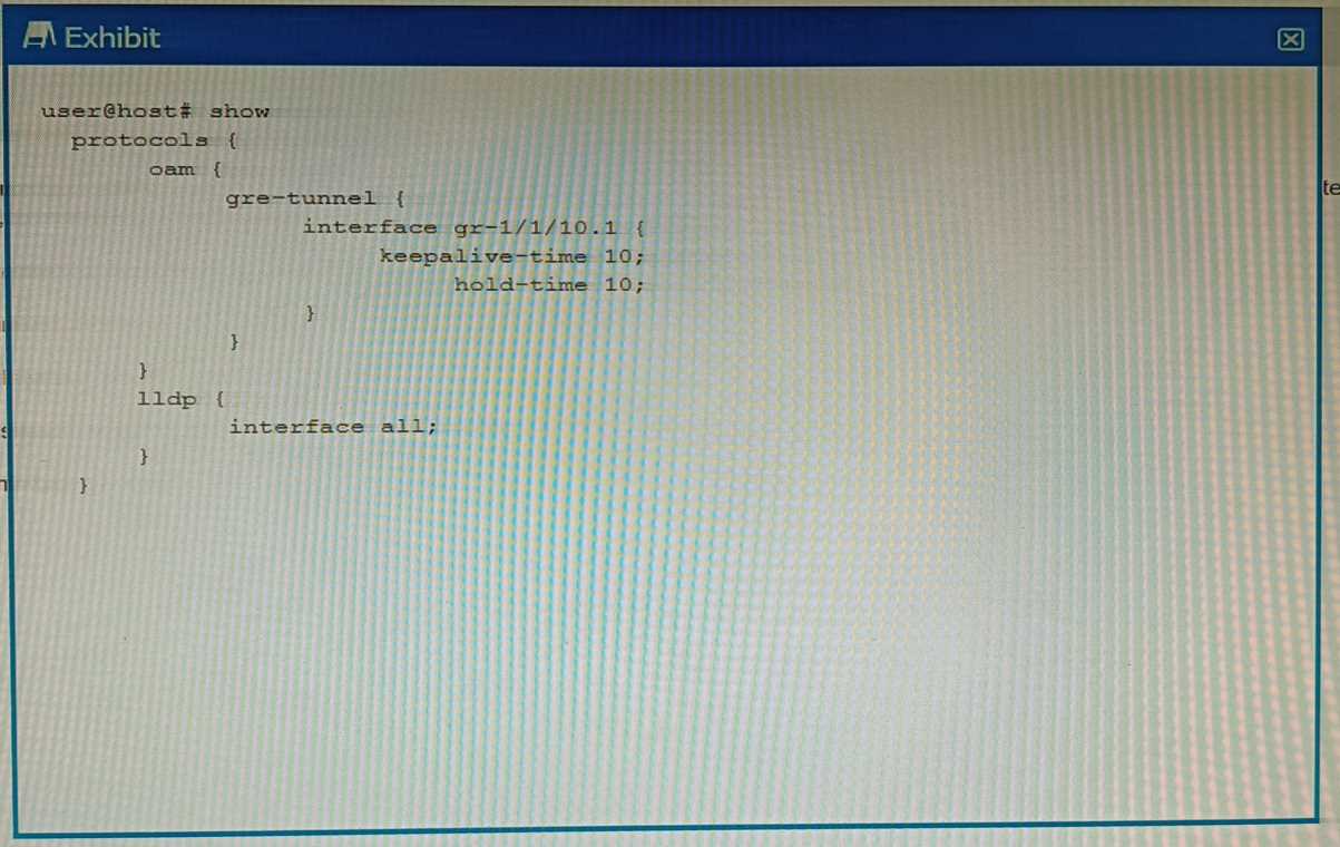
You have configured a GRE tunnel. To reduce the risk of dropping traffic, you have configured a
keepalive OAM probe to monitor the state of the tunnel; however, traffic drops are still occurring.
Referring to the exhibit, what is the problem?
- A. For GRE tunnels, the OAM protocol requires that the BFD protocols also be used.
- B. The "event link-adjacency-loss" option must be set.
- C. LLDP needs to be removed from the gr-1/1/10.1 interface.
- D. The hold-time value must be two times the keepalive-time value
Answer:
D
Explanation:
A keepalive OAM probe is a mechanism that can be used to monitor the state of a GRE tunnel and
detect any failures in the tunnel path. A keepalive OAM probe consists of sending periodic packets
from one end of the tunnel to the other and expecting a reply.
If no reply is received within a
specified time, the tunnel is considered down and the line protocol of the tunnel interface is changed
to down1
.
To configure a keepalive OAM probe for a GRE tunnel, you need to specify two parameters: the
keepalive-time and the hold-time. The keepalive-time is the interval between each keepalive packet
sent by the local router.
The hold-time is the maximum time that the local router waits for a reply
from the remote router before declaring the tunnel down2
.
According to the Juniper Networks documentation, the hold-time value must be two times the
keepalive-time value for a GRE tunnel2
. This is because the hold-time value must account for both
the round-trip time of the keepalive packet and the processing time of the remote router. If the hold-
time value is too small, it may cause false positives and unnecessary tunnel flaps.
In the exhibit, the configuration shows that the keepalive-time is set to 10 seconds and the hold-time
is set to 15 seconds for the gr-1/1/10.1 interface. This means that the local router will send a
keepalive packet every 10 seconds and will wait for 15 seconds for a reply from the remote router.
However, this hold-time value is not two times the keepalive-time value, which violates the
recommended configuration. This may cause traffic drops if the remote router takes longer than 15
seconds to reply.
Therefore, option D is correct, because the hold-time value must be two times the keepalive-time
value for a GRE tunnel.
Option A is incorrect, because BFD is not required for GRE tunnels; BFD is
another protocol that can be used to monitor tunnels, but it is not compatible with GRE
keepalives3
.
Option B is incorrect, because the “event link-adjacency-loss” option is not related to
GRE tunnels; it is an option that can be used to trigger an action when a link goes down4
.
Option C is
incorrect, because LLDP does not need to be removed from the gr-1/1/10.1 interface; LLDP is a
protocol that can be used to discover neighboring devices and their capabilities, but it does not
interfere with GRE tunnels5
.
Reference:
:
Configuring Keepalive Time and Hold time for a GRE Tunnel Interface 2: keepalive | Junos OS |
Juniper Networks 3: Configuring Bidirectional Forwarding Detection 4: event link-adjacency-loss |
Junos OS | Juniper Networks 5
: Understanding Link Layer Discovery Protocol
Question 15
Exhibit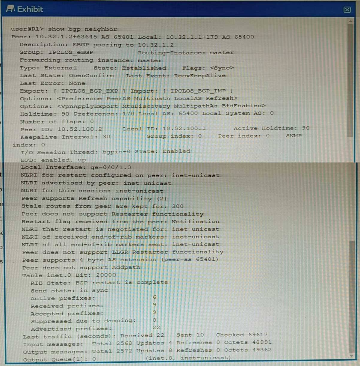
You are a network operator troubleshooting BGP connectivity.
Which two statements are correct about the output shown in the exhibit? (Choose two.)
- A. Peer 10.32.1.2 is configured for AS 63645.
- B. The BGP session is not established.
- C. The R1 is configured for AS 65400.
- D. The routers are exchanging IPv4 routes.
Answer:
BC
Explanation:
Option B suggests that the BGP session is not established. This is correct because in the output, the
state of the BGP session is shown as “Idle”.
In BGP, an “Idle” state means that the BGP session is not
currently established1
.
Option C suggests that R1 is configured for AS 65400.
This is also correct because in the output, it’s
shown that the local AS number is 654001
.
The local AS number represents the Autonomous System
(AS) number of the router on which you’re checking the BGP session1
.