dell d-psc-mn-01 practice test
Dell PowerScale Maintenance Version 2
Question 1
A customer notices a platform engineer intentionally leaving a 1U gap underneath a Dell PowerScale
H400 chassis during racking and stacking What is the purpose of the gap?
- A. Backend Ethernet switch
- B. Cable management tray
- C. Location to install archive nodes
- D. Required blanking panel for node separation
Answer:
B
Explanation:
During the installation of Dell PowerScale H400 nodes, it is standard practice to leave a 1U gap
underneath the chassis to accommodate the Cable Management Tray (CMT). The Cable
Management Tray is essential for organizing and supporting the network and power cables
connected to the node. Proper cable management ensures that cables are neatly routed, reduces
stress on the connectors, and prevents obstruction of airflow within the rack.
According to the Dell PowerScale Hardware Installation and Planning Guide, the inclusion of a Cable
Management Tray improves serviceability and maintains optimal airflow by preventing cables from
hanging in front of the equipment or blocking ventilation paths. By intentionally leaving a 1U gap,
the platform engineer ensures that the Cable Management Tray can be installed without interfering
with the node's operation or the rack's structural integrity.
Reference:
Dell PowerScale Hardware Installation and Planning Guide
Best Practices for Cable Management in Dell PowerScale Systems
Question 2
Which cluster interface provides the most detailed network traffic statistics and enables file and
directory operations on the cluster?
- A. Web console
- B. Serial console
- C. Platform API
- D. CLI
Answer:
D
Explanation:
The Command Line Interface (CLI) provides the most comprehensive and detailed interaction with a
Dell PowerScale cluster. Through the CLI, administrators have access to a wide range of commands
that offer detailed network traffic statistics, system performance metrics, and the ability to perform
granular file and directory operations.
While the Web console offers a user-friendly graphical interface for cluster management, it may not
provide the same level of detail or the full set of functionalities available in the CLI. The Serial
console is primarily used for initial setup or troubleshooting when network access is unavailable. The
Platform API allows for programmatic access but requires additional development effort to utilize.
The CLI is accessible via SSH and provides tools like isi statistics for detailed performance metrics and
isi commands for file system operations. This makes it the most powerful interface for administrators
needing in-depth information and control over the cluster.
Reference:
Dell PowerScale OneFS Command-Line Administration Guide
Dell PowerScale OneFS CLI Reference Guide
Question 3
A platform engineer is connecting a new Dell PowerScale F600 node to the frontend switch in an
existing cluster with legacy nodes.
How should the network cables be connected?
- A. From the PCIe slot 1 to the frontend Ethernet switch
- B. From the PCIe slot 3 to the frontend Ethernet switch
- C. From the PCIe slot 1 to the frontend InfiniBand switch
- D. From the PCIe slot 3 to the frontend InfiniBand switch
Answer:
A
Explanation:
When connecting a Dell PowerScale F600 node to the frontend network in an existing cluster with
legacy nodes, it's important to follow the correct cabling practices to ensure network compatibility
and optimal performance.
The F600 node uses PCIe slot 1 for frontend (client) network connections. This slot supports Ethernet
network interfaces that handle client traffic. PCIe slot 3 is typically reserved for backend (cluster
interconnect) networking. Since the cluster includes legacy nodes, and assuming they use Ethernet
for frontend connectivity, the F600 should connect its frontend network interfaces from PCIe slot 1 to
the frontend Ethernet switch.
Connecting the cables from PCIe slot 1 to the frontend Ethernet switch ensures that the F600 node
properly communicates with clients and integrates seamlessly into the existing cluster network
infrastructure.
Reference:
Dell PowerScale F600 Technical Specifications Guide
Dell PowerScale Network Configuration Guide
Best Practices for Adding Nodes to an Existing Dell PowerScale Cluster
Question 4
A platform engineer connected to a Dell PowerScale F600 node using a serial connection. The session
is unresponsive.
What action must the engineer take?
- A. Restart the server using the front panel power button.
- B. Check the settings of the serial connection.
- C. Replace the serial cable with a new one.
- D. Update the node firmware to the latest release
Answer:
B
Explanation:
When a platform engineer connects to a Dell PowerScale F600 node using a serial connection and
the session is unresponsive, the first action should be to check the settings of the serial connection.
Serial communication requires specific configuration parameters to establish a successful connection.
An incorrect setting can result in an unresponsive session.
The standard serial connection settings for Dell PowerScale nodes are:
Baud Rate: 115200
Data Bits: 8
Parity: None
Stop Bits: 1
Flow Control: None
Steps to resolve the issue:
Verify Serial Port Configuration:
Open your terminal emulator software (e.g., PuTTY, Tera Term).
Check that the serial port settings match the required parameters.
Confirm Physical Connections:
Ensure that the serial cable is securely connected to both the laptop and the node's serial port.
Test the Serial Cable:
If possible, test the cable with another device to rule out a faulty cable.
Restarting the server or updating firmware is unnecessary at this stage and could introduce
additional issues. Replacing the serial cable should only be considered after confirming that the
settings and connections are correct.
Reference:
Dell PowerScale Hardware Installation and Planning Guide – Serial Connection Settings
Dell PowerScale OneFS CLI Administration Guide – Accessing the Cluster Through a Serial Connection
Dell Knowledge Base Article – Troubleshooting Serial Console Access
Question 5
DRAG DROP
A platform engineer is creating a Dell PowerScale cluster using the Configuration Wizard. They have
selected the Create a new cluster option. What Is the correct sequence of steps to create the cluster?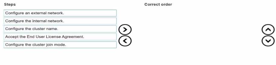
Answer:
Explanation:
The correct sequence is:
Accept End User License Agreement
Configure cluster name
Configure cluster join mode
Configure internal network
Configure external network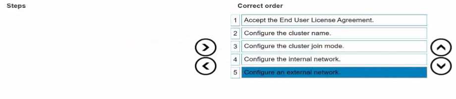
When creating a new Dell PowerScale cluster using the Configuration Wizard, the steps must be
performed in a specific sequence to ensure proper setup and functionality. Below is the detailed
order of the steps with explanations and references to Dell PowerScale documentation.
1. Accept End User License Agreement
Purpose:
Before any configuration can begin, you must accept the End User License Agreement (EULA) to
comply with legal requirements and proceed with the cluster setup.
Action:
Review the EULA presented in the Configuration Wizard.
Select the option to accept the terms and conditions.
Dell PowerScale Reference:
Dell EMC PowerScale OneFS Installation Guide
Chapter: Initial Configuration
The Configuration Wizard begins by displaying the EULA, which must be accepted to continue.
Best Practices:
Carefully read the EULA to understand your rights and obligations.
2. Configure Cluster Name
Purpose:
Assigning a cluster name is essential for identification and management purposes within your
network environment.
Action:
Enter a unique and descriptive name for the cluster when prompted.
Dell PowerScale Reference:
Dell EMC PowerScale OneFS Installation Guide
Section: Configuring Cluster Settings
After accepting the EULA, the wizard prompts for cluster-specific settings, starting with the cluster
name.
Best Practices:
Use a naming convention that aligns with your organization's standards.
Ensure the cluster name is DNS-resolvable if necessary.
3. Configure Cluster Join Mode
Purpose:
Determine whether to create a new cluster or join an existing one.
Since you are creating a new cluster, you need to select the appropriate join mode.
Action:
Choose "Create a new cluster" from the available options.
Dell PowerScale Reference:
Dell EMC PowerScale OneFS Installation Guide
Section: Cluster Creation Options
The wizard asks whether to create a new cluster or join an existing one.
Best Practices:
Verify that all nodes intended for the cluster are correctly cabled and powered on.
4. Configure Internal Network
Purpose:
Set up the internal networking (back-end network) that enables communication between nodes
within the cluster.
Critical for cluster operations, data replication, and management traffic.
Action:
Configure settings for internal interfaces int-a and int-b.
Assign IP address ranges and netmasks as required.
Dell PowerScale Reference:
Dell EMC PowerScale Networking Configuration Guide
Chapter: Configuring Internal Networks
Details on setting up the internal network interfaces during cluster creation.
Best Practices:
Use separate subnets for int-a and int-b to enhance redundancy.
Ensure that the internal network is isolated from external networks for security.
5. Configure External Network
Purpose:
Establish the external networking (front-end network) that allows clients and services to access the
cluster.
Action:
Configure settings for external network interfaces.
Assign IP addresses, netmasks, gateways, and DNS information.
Dell PowerScale Reference:
Dell EMC PowerScale Networking Configuration Guide
Chapter: Configuring External Networks
Provides guidance on setting up external interfaces after internal networking is configured.
Best Practices:
Plan IP addressing to avoid conflicts within your network.
Configure SmartConnect zones if required for load balancing and failover.
Additional Notes:
Sequence Importance:
Following this sequence ensures that foundational settings are established before dependent
configurations.
For example, internal networking must be configured before external networking to ensure proper
node communication.
Validation and Testing:
After completing the Configuration Wizard, validate the cluster setup by checking node status and
network connectivity.
Use the OneFS web administration interface or CLI commands to verify configurations.
Reference to Dell PowerScale Documentation:
Dell EMC PowerScale OneFS Installation Guide
Provides step-by-step instructions for initial cluster setup.
Dell EMC PowerScale Networking Configuration Guide
Offers detailed information on networking configurations and best practices.
Dell EMC PowerScale OneFS Administration Guide
Useful for advanced configurations and cluster management post-installation.
Conclusion:
By following the sequence outlined above, the platform engineer can successfully create a new Dell
PowerScale cluster using the Configuration Wizard. Each step builds upon the previous one, ensuring
a robust and properly configured cluster ready for operation.
Question 6
A platform engineer must replace a failed chassis on a Dell PowerScale Gen6 cluster. What must the
engineer do after powering off the nodes?
- A. Remove the drive sleds, label them for identification, and place the drive sleds In the newly installed chassis.
- B. Remove the drive sleds and motherboard and transfer them to the new chassis.
- C. Remove the drives and compute modules and reimage each drive before installing them in the chassis.
- D. Remove the drives, install the chassis, and place the drives in the new chassis.
Answer:
A
Explanation:
When replacing a failed chassis in a Dell PowerScale Gen6 cluster, it's critical to preserve the data and
configuration by maintaining the exact placement of the drive sleds. After powering off the nodes,
the engineer should:
Remove Drive Sleds:
Carefully remove each drive sled from the failed chassis.
Label for Identification:
Label each drive sled with its corresponding slot number or unique identifier.
Install New Chassis:
Mount the new chassis in the rack where the failed one was located.
Reinstall Drive Sleds:
Insert the labeled drive sleds into the same slots in the new chassis.
Power On Nodes:
Power on the nodes and verify that they boot correctly and rejoin the cluster.
This procedure ensures that the drives remain in their original configuration, preserving data
integrity and cluster settings. There's no need to transfer motherboards or reimage drives, as these
actions could disrupt cluster operations and lead to data loss.
Reference:
Dell PowerScale Hardware Replacement Guide – Chassis Replacement Procedures
Dell PowerScale OneFS Administration Guide – Best Practices for Hardware Maintenance
Dell Knowledge Base Article – Preserving Drive Order During Chassis Replacement
Question 7
Dell Technical Support has requested a part be sent back to Dell Logistics to be studied.
Which process or document musi be completed before sending the part back?
- A. WWFA
- B. DTFA
- C. DMR
- D. CDMR
Answer:
C
Explanation:
When Dell Technical Support requests a part to be sent back for analysis, a Defective Material Return
(DMR) process must be completed. The DMR process involves several key steps:
Receive DMR Authorization:
Dell Technical Support provides a DMR number and return instructions.
Complete Required Documentation:
Fill out any forms detailing the part's serial number, failure symptoms, and troubleshooting steps
taken.
Prepare the Part for Shipment:
Properly package the defective part using anti-static materials and cushioning to prevent further
damage.
Include DMR Documentation:
Attach the DMR paperwork with the shipment to ensure correct processing.
Ship the Part:
Send the package to the designated Dell Logistics center.
Completing the DMR process allows Dell to study the defective part, which can lead to product
improvements and enhanced support services.
Reference:
Dell PowerScale Field Replacement Unit (FRU) Procedures – DMR Process
Dell Logistics Return Guidelines – Shipping and Documentation Requirements
Dell Technical Support Policies – Defective Material Return Instructions
Question 8
What must be enabled in SMB to ensure nondisruptive upgrades?
- A. SMB multichannel
- B. SMB encryption
- C. SMB direct
- D. SMB continuous availability
Answer:
D
Explanation:
To ensure nondisruptive upgrades in an SMB environment, SMB Continuous Availability (CA) must be
enabled. SMB CA allows file shares to remain accessible without interruption during planned
maintenance or unexpected node failures.
Key features of SMB Continuous Availability:
Transparent Failover:
Client sessions persist seamlessly when the SMB service fails over to another node.
State Preservation:
Open files, locks, and session states are maintained during the failover.
High Availability:
Enhances the cluster's ability to provide uninterrupted service.
Steps to enable SMB Continuous Availability:
Verify OneFS Version:
Ensure the cluster is running OneFS version that supports SMB 3.0 or higher.
Enable SMB CA on the Cluster:
Use the OneFS WebUI or CLI to enable Continuous Availability for SMB shares.
Configure SMB Shares:
Set the "Continuous Availability" option on the specific SMB shares that require it.
Client Requirements:
Clients must be running Windows 8 or Windows Server 2012 (or later) to support SMB CA.
By enabling SMB Continuous Availability, upgrades and maintenance can be performed without
disrupting client access to file shares.
Reference:
Dell PowerScale OneFS SMB Administration Guide – Configuring SMB Continuous Availability
Dell PowerScale OneFS Upgrade Planning Guide – Ensuring Nondisruptive Upgrades
Microsoft SMB Protocol Documentation – SMB 3.0 Features
Question 9
Windows clients cannot connect using the fully qualified domain name when testing the connectivity
of a newly created cluster. What connection test identifies the problem?
- A. DNS
- B. NFS Mount
- C. Mapping a Windows drive
- D. WebUI using IP address
Answer:
A
Explanation:
When Windows clients cannot connect to a newly created cluster using the fully qualified domain
name (FQDN), but can connect using the IP address, it indicates a DNS resolution issue. Conducting a
DNS connection test can help identify and resolve the problem.
Steps to test and troubleshoot DNS:
Verify DNS Configuration on the Cluster:
Ensure that the cluster's FQDN is correctly configured in the OneFS settings.
Check DNS Records:
Use the nslookup or dig command from a client machine to verify that the FQDN resolves to the
correct IP address.
Example:
nslookup cluster.example.com
Inspect Client DNS Settings:
Confirm that the clients are using the correct DNS servers.
Update DNS Entries if Necessary:
If the FQDN does not resolve correctly, update the DNS zone files or entries on the DNS server.
Flush DNS Cache:
On the client machine, flush the DNS cache to remove outdated entries.
ipconfig /flushdns
Test Connectivity Again:
Attempt to reconnect using the FQDN to verify that the issue is resolved.
By identifying that DNS is the root cause, appropriate steps can be taken to correct the DNS entries,
ensuring clients can connect to the cluster using the FQDN.
Reference:
Dell PowerScale Networking Guide – DNS Configuration and Best Practices
Dell PowerScale OneFS Administration Guide – Managing Network and DNS Settings
Troubleshooting Connectivity Issues – Dell Knowledge Base Article
Question 10
An engineer runs ini_reformat_node command.
What are they attempting to do?
- A. Reformat the mirrored FEC data.
- B. Reformat a node quickly to repurpose a node.
- C. Reformat the mirrored journals.
- D. Reformat a node to securely erase all data.
Answer:
D
Explanation:
The isi_reformat_node command is a utility used on Dell PowerScale (Isilon) clusters to reformat a
node and securely erase all data on it. This command initializes the node's storage media, effectively
wiping all user data, metadata, and system configurations from the node's drives.
Purpose of isi_reformat_node:
Secure Data Erasure: It ensures that all data is securely erased, which is essential when
decommissioning a node or repurposing it for a different use.
Node Recovery or Repurposing: It prepares the node for re-integration into the cluster or for use in a
different cluster by resetting it to a factory-like state.
Usage Scenarios:
Decommissioning a Node: When permanently removing a node from a cluster and ensuring no
residual data remains.
Repurposing Hardware: When reassigning the node to a different cluster or role and needing to
eliminate all previous configurations and data.
Recovering from Corruption: In cases where the node's data is irreparably corrupted, reformatting
allows for a clean start.
Key Points:
Data Loss Warning: Running isi_reformat_node will result in complete data loss on that node. It's
crucial to ensure that the data is backed up or that the node's data is no longer needed.
Cluster Impact: Before reformatting, the node should be appropriately prepared, and the cluster
should be informed to avoid any data protection issues.
Secure Erasure Standards: The command follows secure erasure standards to prevent data recovery
through forensic methods.
Reference:
Dell PowerScale OneFS CLI Administration Guide – Details on using isi_reformat_node and its
implications.
Dell PowerScale OneFS Administration Guide – Procedures for safely removing and reformatting
nodes.
Dell Knowledge Base Article – Best practices for decommissioning and reformatting nodes in a
PowerScale cluster.
Question 11
An existing PowerScale cluster consists of four A300 and three F600 nodes.
What is the minimum number of nodes an engineer can add to expand both node pools?
- A. txA300 2xF600
- B. 2xA300 2xF600
- C. 3xF600 4xA300
- D. 2xA300 1x F600
Answer:
D
Explanation:
In a Dell PowerScale cluster that consists of four A300 nodes and three F600 nodes, expanding both
node pools requires adding nodes to each pool. The minimum number of nodes an engineer can add
to expand both node pools is determined by the following factors:
Minimum Node Addition:
PowerScale clusters allow the addition of nodes one at a time to existing node pools.
However, to maintain balanced performance and capacity, it's recommended to add nodes in pairs or
according to specific guidelines for each node type.
Node Pool Requirements:
A300 Nodes (Capacity Tier):
Designed for high-capacity storage needs.
Adding at least two A300 nodes helps maintain even data distribution and protection levels.
F600 Nodes (Performance Tier):
Designed for high-performance all-flash storage requirements.
Adding at least one F600 node can expand the performance tier, but adding two would be optimal
for balance.
Minimum Nodes to Expand Both Pools:
Option D suggests adding 2xA300 and 1xF600, totaling three nodes.
This is the minimum number among the options provided that allows expansion of both node pools.
Why Option D is Correct:
Meets Minimum Addition Recommendations:
Adding 2xA300 nodes enhances capacity while maintaining data protection schemes like FEC
(Forward Error Correction).
Adding 1xF600 node increases performance capacity with minimal investment.
Ensures Data Protection and Performance:
Adequate node addition helps in maintaining the cluster's data protection policies and performance
characteristics.
Reference:
Dell PowerScale OneFS Administration Guide – Guidelines on adding nodes to existing clusters.
Dell PowerScale Best Practices – Recommendations for node additions and cluster expansions.
Dell PowerScale Technical Specifications – Details on node types and their roles within a cluster.
Question 12
What type of upgrade on a Dell PowerScale cluster requires the least amount of time?
- A. Simultaneous
- B. Parallel
- C. Rolling
- D. Automatic
Answer:
A
Explanation:
A simultaneous upgrade on a Dell PowerScale cluster involves upgrading all nodes at the same time.
This method requires the least amount of time compared to other upgrade types because it
minimizes the total duration by handling the upgrade process concurrently across the entire cluster.
Types of Upgrades:
Simultaneous Upgrade:
Definition: All nodes are upgraded at the same time.
Advantages:
Fastest upgrade method.
Reduces total upgrade time significantly.
Disadvantages:
Requires cluster downtime; not suitable for environments that need continuous availability.
Rolling Upgrade:
Definition: Nodes are upgraded one at a time or in small groups.
Advantages:
No cluster downtime; services remain available.
Disadvantages:
Takes longer to complete as each node is upgraded sequentially.
Parallel Upgrade:
Definition: Nodes are upgraded in parallel batches.
Advantages:
Balances upgrade speed and availability.
Disadvantages:
May still require some service interruption.
Automatic Upgrade:
Definition: The upgrade process is automated but follows the rolling or parallel methodology.
Advantages:
Reduces manual intervention.
Disadvantages:
Upgrade time depends on the underlying method used (rolling or parallel).
Why Simultaneous Upgrade Requires the Least Amount of Time:
Concurrent Processing: Upgrading all nodes at once leverages parallelism, drastically reducing the
total time needed.
No Sequential Steps: Eliminates the wait time associated with upgrading nodes one after another.
Use Case Considerations: Suitable for non-production clusters or environments where downtime is
acceptable.
Important Considerations:
Cluster Downtime: Simultaneous upgrades will render the cluster unavailable during the process.
Risk Management: Any issues during the upgrade can affect the entire cluster; thorough planning
and backups are essential.
Reference:
Dell PowerScale OneFS Upgrade Planning and Process Guide – Details on upgrade methods and best
practices.
Dell PowerScale Administration Guide – Instructions and considerations for performing cluster
upgrades.
Best Practices for OneFS Upgrades – Recommendations for selecting the appropriate upgrade
method based on environment needs.
Question 13
Refer to the exhibit.
An engineer replaced the drive in C1. They run the isi devices drive list command and obtain the
output that is shown.
What action must the engineer take?
- A. Run the 1 = 1 devices drive add c1 command.
- B. Run the isi devices drive format C1 command.
- C. Contact Dell support.
- D. Update the drive firmware.
Answer:
B
Explanation:
In the output of the isi devices drive list command shown in the exhibit, the drive in location C1 is
marked as "USED," with the serial number VRKL242P. This indicates that the drive has been replaced
but has not yet been initialized or formatted for use within the PowerScale cluster.
To make the drive usable, it must be formatted. The correct procedure to follow is to use the isi
devices drive format command, specifying the drive location (C1 in this case). This will prepare the
drive for use in the cluster, ensuring that it is recognized and available for OneFS to start writing data
to it.
Steps to format the drive:
Log in to the OneFS cluster using an SSH session with an account that has the necessary privileges.
Run the following command to format the new drive:
bash
Copy code
isi devices drive format C1
This command will format the drive located at C1, making it available for use in the cluster.
After the format is complete, verify that the drive is now in a HEALTHY state by running:
isi devices drive list
This should display the new status of the drive as HEALTHY, indicating that it has been successfully
formatted and is ready for data operations.
This process is outlined in Dell’s PowerScale Administration Guide and ensures the correct
initialization of new or replaced drives.
Question 14
What is the isi diagnostics gather command used for?
- A. Diagnose the CPU.
- B. Diagnose the TPM
- C. Gather performance data.
- D. Gather cluster logs
Answer:
D
Explanation:
The isi diagnostics gather command is used in Dell PowerScale (formerly known as Isilon) clusters to
collect comprehensive diagnostic information, including system logs, configuration files, and other
pertinent data from all nodes in the cluster. This gathered information is essential for
troubleshooting and is often requested by Dell Support to diagnose and resolve issues.
Purpose of isi diagnostics gather:
The command aggregates logs and diagnostic information across the entire cluster.
It collects data such as event logs, configuration settings, and performance metrics.
Use Cases:
Troubleshooting: When experiencing issues with the cluster, this command helps in collecting
necessary data for analysis.
Support Assistance: Dell Support may request the output from this command to assist in diagnosing
cluster problems.
Process:
When executed, the command generates a single compressed file containing all the collected
information.
The file can be securely sent to Dell Support for further analysis.
Dell PowerScale Reference:
Dell EMC PowerScale OneFS CLI Administration Guide: This guide provides detailed information on
command-line utilities, including isi diagnostics gather.
Dell EMC Knowledge Base Articles: Articles related to troubleshooting often reference the use of isi
diagnostics gather to collect logs.
Question 15
Which model is a part of the Isilon Gen6 platform?
- A. F600
- B. F810
- C. F900
- D. F200
Answer:
B
Explanation:
The Isilon Gen6 platform includes several models designed to meet various performance and
capacity needs. The F810 is part of the Gen6 family and is specifically an all-flash node offering high
performance and efficiency.
Isilon Gen6 Platform Overview:
Gen6 platforms are known for their modular architecture and enhanced performance.
They offer improved scalability and efficiency over previous generations.
F810 Model Details:
All-Flash Storage: The F810 is an all-flash node, providing low latency and high throughput.
High Capacity: It offers large storage capacities suitable for demanding workloads.
Use Cases: Ideal for high-performance computing, real-time analytics, and workloads requiring rapid
data access.
Other Models:
F600 and F900: These are part of the Dell EMC PowerScale family introduced after the Isilon
rebranding and are not Gen6 Isilon models.
F200: Also part of the newer PowerScale lineup, not associated with the Isilon Gen6 platform.
Dell PowerScale Reference:
Dell EMC Isilon Gen6 Technical Overview: Documentation outlining the features and models included
in the Gen6 series.
Dell EMC Isilon F810 Data Sheet: Provides specifications and details about the F810 model.
Product Support Pages: Offer information on the various models within the Isilon and PowerScale
families.